Machine vision systems have four main coordinate systems:
1. World Coordinate System
2. Camera Coordinate System
3. Image Coordinate System
4. Pixel Coordinate System
Table of Contents
World coordinate system
The world coordinate system (Xw, Yw, Zw) is the reference system for the position of the target object. The origin can be freely set according to computational convenience, such as at the center of the camera lens, the central axis of a mechanical arm, or the geometric center of an AGV (Automated Guided Vehicle). Its major functions are:
(1) Defining the 3D coordinates of objects;
(2) Determining the position of calibration objects based on the origin during calibration;
(3) Providing the position of the camera coordinate system relative to the world coordinate system, thereby determining the coordinate relationship between two or more cameras.
Camera coordinate system
The camera coordinate system (Xc, Yc, Zc) is the coordinate system from the camera’s own perspective, with the origin at the optical center of the camera. The Z-axis is parallel to the optical axis of the camera, i.e., the direction in which the camera lens projects.
Image Coordinate System
The image coordinate system (x, y) is on the imaging plane. The origin of the image coordinate system is usually the midpoint of the imaging plane in mm.
Pixel coordinate system
The pixel coordinate system (u, v) in the imaging plane uses pixels as units, with the origin at the top-left corner of the imaging plane.
Relationship among coordinate systems
When determining the position of an object in an image, how do we enable the robotic arm to reach the actual position in space to grasp it? This requires coordinate conversion. The conversion from pixel points to space points is the reverse of the conversion from space points to pixel points. We first explain the derivation process of the latter.
Image coordinate system and pixel coordinate system
The relationship between the image coordinate system and the pixel coordinate system is as follows:
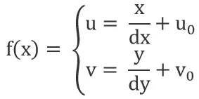
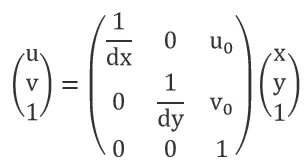
Notes:dx represents the width of one pixel (in the x-direction), with the same unit as x. x/dx represents the number of pixels along the x-axis, similarly y/dy represents the number of pixels along the y-axis. (u0, v0) is the center of the image plane. The relationship show in the figure below:
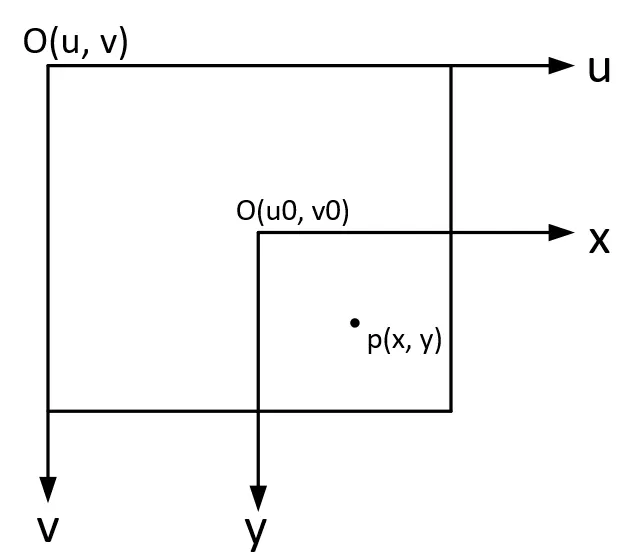
Converting the above relationship into matrix form, as show in the figure below:
Camera coordinate system and pixel coordinate system
The transition from the camera coordinate system to the image coordinate system is a process from 3D coordinates to 2D coordinates (3D -> 2D), known as projection transformation. To determine their relationship, extend the normal image coordinates (x, y) to homogeneous coordinates (x, y, 1). A point in space, when projected onto the image plane, aligns with the optical center of the camera on a straight line. Establish the camera coordinate system with the optical center as the origin:
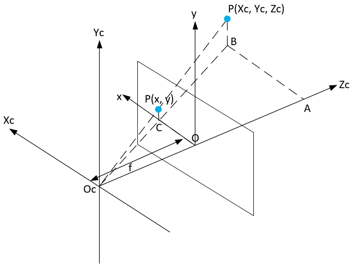
Based on the relationship of similar triangles, we obtain the following results:

Notes: f is the focal length of the camera (the distance from the optical center of the camera to the imaging plane).
Expressed in matrix form:

The relationship between image points and space points is obtained:

World coordinate system and camera coordinate system
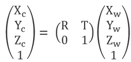
The world coordinates (Xw, Yw, Zw) and camera coordinates (Xc, Yc, Zc) are both three-dimensional coordinates (right-hand system, with three axes perpendicular to each other). The relationship between the two coordinate systems is a rigid body transformation (rigid body transformation: the rotation and translation of a geometric object when the object does not deform). Imagine two coordinate systems, A and B. To convert coordinates from coordinate system A to coordinate system B, first, rotate the A coordinate system arbitrarily about its origin so that its x, y, and z axes are parallel and in the same direction as the B coordinate axes. Then, translate the origin of the AB coordinate system by the straight-line distance. This rotation and translate determine the relationship between the two three-dimensional coordinates. The relationship between the two coordinate systems can be represented by the following equation:

Notes: The rotation matrix R can be considered the result of the pointwise multiplication of the three rotation matrices of space coordinates along the X, Y, and Z axes.
When rotating θ degrees around the Z-axis, the relationship between the new and old coordinates is:

Represented in matrix form:

Similarly, rotating by φ and ω degrees around the X and Y axes, respectively, gives:
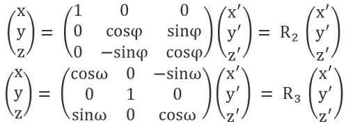
Thus, the rotation matrix R = R1 x R2 x R3, with a dimension of 3×3. T is the translation matrix, with a dimension of 3×1.
Expanded to homogeneous coordinates:
From world coordinates to pixel coordinates
Combining the above derivation processes, the world coordinates (Xw, Yw, Zw) -> camera coordinates (Xc, Yc, Zc) -> image coordinates (x, y) -> pixel coordinates (u, v). This sequence can be represented by continuously left-multiplying the next step in matrix form:

The product of the first two matrices on the right side of the equation is called the camera intrinsic parameters. The third matrix is called the camera extrinsic parameters. The camera calibration aims to solve the intrinsic and extrinsic parameters of the camera.
Detailed explanation of intrinsic and extrinsic parameters
Intrinsic parameters
Intrinsic parameters include focal length, decenter coefficient, and skew coefficient.
(1) Focal length: Focal length is the distance between the focal point of the lens and the sensor. It projects the 3D points of the RGB camera onto a 2D image plane in the camera.
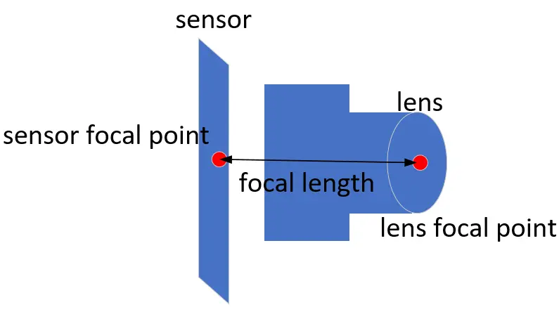
(2) Decenter coefficient: It refers to the offset caused by the misalignment of lens elements during camera assembly.
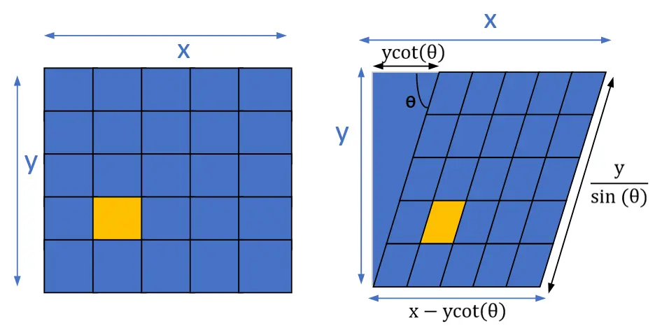
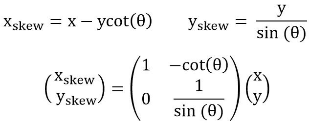
(3) Skew Coefficient: When the 2D image plane is skew, i.e., the angle between the x and y axes is not 90 degrees, another transformation is needed, from the rectangular plane to the skew plane (before the image to pixel coordinate conversion). Assuming the angle between the x and y axes is θ, the transformation of a point from the rectangular plane to the skew plane can be performed as follows.
We can decompose the intrinsic matrix into a series of scaling and translation transformations, corresponding to axis skew, focal length, and decenter coefficient.

Note: fx, fy: Pixel focal length; s: Skew coefficient; cx, cy: Decenter coefficient.
Extrinsic parameters
Extrinsic parameter represents the relative position and orientation between the ToF(Time-of-Flight) camera and the RGB camera, consisting of 3D rotation and 3D translation. A point denoted as pToF(XToF, YToF, ZToF) in the ToF coordinate system, after conversion, is represented as PRGB(XRGB, YRGB, ZRGB) in the RGB coordinate system.
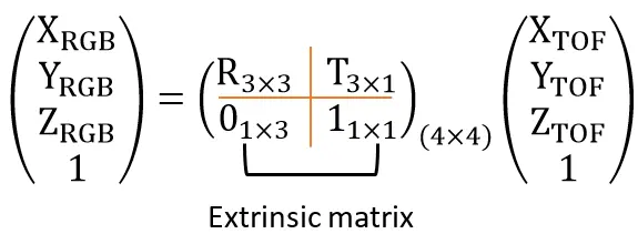
In summary, for the position PToF(XToF, YToF, ZToF) of the object in the ToF camera, the position p(x, y, z) in the RGB camera can be calculated through the intrinsic matrix and extrinsic matrix.


How to convert depth map into point cloud map
The point cloud transformation matrix converts each pixel in a depth image into a 3D point in space, forming a point cloud. With a known intrinsic of a camera system, the formula for the point cloud transformation matrix is as follows:
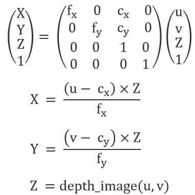
Where:
Z is the depth at pixel (u,v);
X and Y are the corresponding point coordinates in the 3D space;
Cx and Cy are the coordinates of the optical center (principal point);
fx and fy are the focal lengths along the x and y axes respectively.
By applying this matrix, each pixel can be mapped into a three-dimensional space, forming a complete point cloud map.


