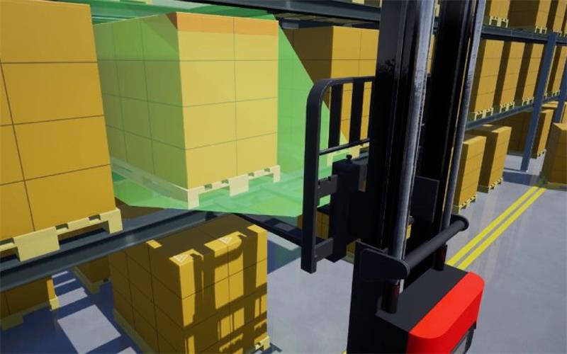
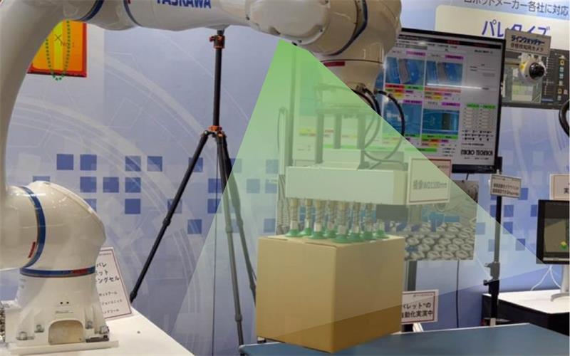
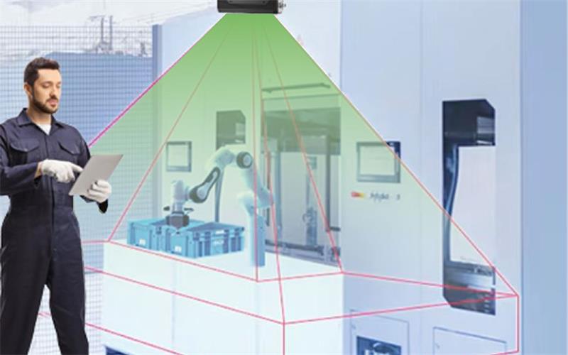
Some changes are quietly happening in our lives, and the speed at which they occur has surpassed the reaction time of our thinking. For example, when you swipe your phone, it automatically activates facial recognition to unlock the screen instantly without manually entering the password. Another example is the AGVs in factory warehouses, which, without human drivers, smoothly complete automatic navigation and obstacle avoidance, placing the correct goods on the correct shelves seamlessly and effortlessly. Have you ever thought about the wonders behind these scenarios? The evolution of our eyes and brain allows us to naturally interact with the 3D world, so we often overlook the reality of 3D. However, to make machines perceive the world as we do, depth-sensing cameras is necessary. In this article, let’s learn about 3D camera technology together!
Table of Contents
The most common types of depth-sensing 3D cameras
Depth sensing cameras provide 3D data related to objects within their field of view (FoV) by measuring the distance between the camera and the objects. In some cases, color information can be added to obtain data usually referred to as RGBD or RGBXYZ. However, this typically requires two cameras: one outputting color information and the other outputting 3D data—they need to be synchronized and calibrated. Therefore, using 3D depth sensors can automatically detect the presence of nearby objects and measure the distance to them in real-time. This helps devices or equipment equipped with 3D depth cameras to achieve autonomous behavior through real-time intelligent decision-making, such as moving, obstacle avoidance, grabbing, or collaboration.
Among all the available depth technologies, the four most popular and commonly used depth-sensing technologies are:
1. Stereo vision
2. Time of Flight, including indirect Time of Flight (iToF) and direct Time of Flight (dToF) implementations.
3. Structured light, divided into stripe structured light and speckle structured light based on the pattern of the structured light.
4. Line Laser
Introduction to the 3D camera principles and comparison of different types of depth-sensing cameras
Stereo vision 3D camera technology
Stereo vision, also known as binocular vision, uses the same 3D camera principle as human eyes to determine the depth of objects—binocular disparity. Two camera lenses are placed at a certain baseline b distance from each other, positioned side by side, just like human eyes. When the stereo vision 3D camera is in operation, it generates two images of the target object (left and right images). By calculating the point-to-point correspondences between these two images, the position of the object in 3D space can be obtained through triangulation. As shown in the figure below:


Note: XL-XR is the disparity.
Pros:
1. Low hardware cost: Stereo cameras can use regular CMOS cameras, which have low hardware requirements and costs.
2. High accuracy and precision at near distances: Based on the principle of triangulation, the depth error of stereo cameras is inversely proportional to the square of the distance, thus providing high depth accuracy and precision at near distances.
Cons:
1. Sensitivity to light: Stereo cameras are highly sensitive to ambient light. Changes in lighting can cause image deviations, affecting matching accuracy and precision. Passive stereo cameras are generally ineffective indoors without natural light. Current active stereo technology can somewhat mitigate this issue.
2. Complex computation: Disparity calculation is resource-intensive, requiring acceleration from GPUs or FPGA devices.
3. Blurred details: Stereo vision technology calculates depth by recognizing textures, often needing to approximate most pixels. This results in blurred depth details, especially at the edges of objects or on uneven surfaces.
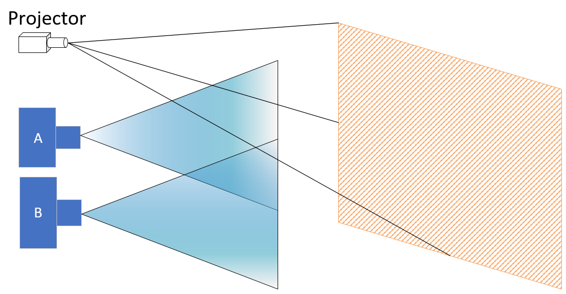
4. Texture dependency: Measurement is less effective for objects with no texture or monotone surfaces because stereo cameras rely on visual features for image matching. Active stereo technology can improve this by projecting textured light patterns onto objects, helping the camera quickly match texture feature points and enhancing recognition in low-light environments. As shown in the figure:
Time of Flight 3D camera technology
Time of Flight (ToF) technology uses an itself light source emitter (laser or LED) to emit artificial light signals (provided by the laser or LED) towards the measured object. It estimates the distance from the object to the camera by measuring the time it takes for the light to travel to the object and reflect back. There are several different implementations of 3D ToF technology for measuring the light’s flight time, usually classified into iToF (indirect Time of Flight) and dToF (direct Time of Flight).
1. iToF
This method indirectly measures the time difference between the emitted and received signals by capturing energy values at different exposure times using sensors. Further, iToF can be divided into two implementation methods: CW-iToF(Continuous Wave-iToF) and P-iToF (Pulsed-iToF).
2. dToF
Emerging in recent years, this 3D camera technique directly measures the time difference between the emission and reception of light pulses. Unlike iToF, which indirectly measures the light’s flight time by using energy values at different exposure times, dToF directly calculates time differences by statistical analysis of multiple measurements.
For more information, please refer to “TN15-Time-of-Flight technology building a real-time 3D depth data environment“.
The working principle diagram of ToF technology is as follows:

Generally speaking, compared to stereo vision, 3D time of flight cameras can provide denser 3D data while operating at higher frame rates. Since they do not require point correspondence matching, they are easier to configure than stereo cameras. In addition, there are the following advantages:
Pros:
1. Wide dynamic range: ToF camera technology can work effectively under various lighting conditions, including low light or no light environments.
2. Long detection distance: 3D Time of Flight(ToF) cameras often have a long detection range, and the distance error ratio does not increase with distance. Specifically, dToF’s detection range can exceed 10 meters.
3. Compact design: This technology allows for smaller form factors, making it easier to integrate into devices like smartphones and gaming consoles.
4. Better for fast-moving scenarios: As mentioned above, ToF cameras have higher frame rates (typically up to 15-30fps), making them better suited for scenarios requiring fast movement.
5. Details retained intact: Unlike stereo vision and structured light technology, the resolution of ToF is determined by the resolution of the ToF sensor, with each pixel being independent and not requiring fitting. Therefore, ToF cameras provide good detail reproduction of objects.
Cons:
1. Low accuracy and precision at near distances: Due to the fast speed of light, their accuracy and precision is not very high, with errors typically in the millimeter range. The accuracy and precision at near distances is especially lower compared to structured light.
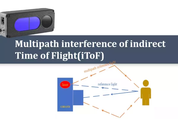
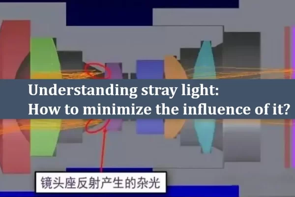
2. Multipath interference and stray light phenomena: Due to its principle, iToF cameras can be affected by multipath interference phenomena and stray light, leading to degraded measurement performance in certain environments. Refer to “TN06-Multipath interference of indirect Time of Flight (iToF)” and “TN11-Understanding stray light: How to minimize the influence of it?“.
3. Sensitivity to reflectivity: The accuracy of time of flight measurement can be affected by the reflectivity of the object’s material. Transparent or highly reflective objects may cause testing errors.
Overall, 3D ToF depth-sensing technology is very powerful for many applications but its limitations need to be considered when choosing specific uses.
Stripe structured light 3D camera technology
Stripe structured light cameras use a laser/LED light source to project known patterns onto the measured object. By analyzing the deformation of its projection combined with triangulation, the distance to the object can be calculated. The working principle of stripe structured light technology is as follows:
Pros:
Generally speaking, stripe structured light cameras can provide higher quality images at near range compared to stereo vision or ToF technology cameras, with higher accuracy and precision, because the projection of patterns provides clear, consistent textures that facilitate point-to-point matching.
Cons:
Since point-to-point matching is still a complex and expensive operation, these cameras usually have a lower frame rate compared to other types of cameras (such as 3D ToF) and are not suitable for high-speed motion scenarios. Additionally, their product cost is often higher.
Speckle structured light 3D camera technology
Speckle structured light cameras use a laser/LED light source to project known patterns (most commonly random speckles) onto the measured object. By analyzing the deformation of its projection combined with triangulation, they calculate the distance to the object. The working principle of speckle structured light technology is as follows:


Pros:
1. Low hardware cost: Speckle structured light cameras use regular CMOS sensors, resulting in lower hardware requirements and costs.
2. High accuracy and precison at near distances: Based on the principle of triangulation, speckle structured light cameras have depth errors inversely proportional to the square of the distance. Therefore, they can provide high depth accuracy at near ranges.
Cons:
1. Light resistance poor: In outdoor bright environments, the emitted speckles can be overwhelmed by ambient light, making recognition impossible.
2. Near detection range: Based on the principle of triangulation, speckle structured light cameras have depth errors inversely proportional to the square of the distance, resulting in poor performance at long distances.
3. Blurred details: Speckle structured light technology calculates depth by recognizing speckle deformations combined with triangulation. Similar to the principle of stereo cameras, it often requires fitting most pixels, leading to blurred depth details, especially at the edges of objects or on uneven surfaces.
Line laser 3D camera technology
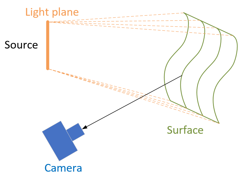
Line laser sensors include a laser emitter, a receiver, and a controller. The laser beam is expanded into a laser line projected onto the measured object’s surface. The receiver (similar to a camera sensor) captures the reflected light and transmits the photoelectric information to the controller. Due to the varying heights of different parts of the object and the angle between the laser and the 3D camera, the laser line is “distorted” into a laser profile when projected onto the object. The controller uses 3D sensor calibration data and custom algorithms to generate height values along the direction of the laser line. The measured object’s surface moves along the Y-axis under the laser line, triggering the sensor to record the contour data of each cross-section, generating and displaying 3D point cloud data. The working principle of line laser technology is as follows:

Pros:
1. High accuracy and precision measurement: Line laser sensors can achieve micron-level resolution, providing accurate measurements of small changes on the object’s surface. Their high linearity and stability ensure measurement accuracy and precision, making them very suitable for applications requiring high accurcay and precision.
Cons:
1. High cost: Compared to some traditional measurement tools, line laser sensors are relatively expensive, which may limit their use in some low-cost applications.
2. High environmental requirements: Line laser sensors need to operate in well-lit and stable environments to ensure measurement accuracy and precision. In low-light or variable lighting conditions, their measurement accuracy and precision may be affected.
3. Safety hazards: Since line laser sensors use laser beams for measurement, improper use or lack of appropriate safety measures can cause harm to humans. Therefore, strict adherence to safety regulations and the implementation of protective measures are necessary during use.
How to choose the right depth camera for specific applications?
In fact, different depth sensing technologies each have their advantages and disadvantages, and there is no single solution suitable for all projects or scenarios. Many stereoscopic cameras now combine more than one depth measurement technology. While structured light performs well in meeting high accuracy and precision requirements, ToF technology acquires and processes data faster and is more widely applicable. Stereo vision, on the other hand, is often more common and affordable. Laser line sensors excel in accuracy and precision but also is much more expensive. To better select the most suitable technology and product, it is helpful to ask the following questions:
1. What are the accuracy and precision requirements for measurement? What is the acceptable error range?
2. What is the measurement distance (working distance of the 3D camera/sensor)?
3. What are the surface characteristics of the measured object? High reflective surface (smooth, light-colored, etc.) or low reflective surface (rough, dark-colored, etc.)?
4. What is the purchase budget?
5. Is real-time data processing required?
| Stereo vision technology | Speckle structured technology | Stripe structured technology | ToF technology | Line Laser technology | |
| Near-range accuracy and precision (within 1m) | ⭐⭐⭐ | ⭐⭐⭐ | ⭐⭐⭐⭐ | ⭐⭐ | ⭐⭐⭐⭐⭐ |
| Long-range accuracy and precision (far1m) | ⭐⭐ | ⭐⭐ | ⭐⭐⭐⭐ | ⭐⭐⭐ | ⭐⭐⭐⭐⭐ |
| Detection distance | ⭐⭐ | ⭐⭐⭐ | ⭐⭐⭐ | ⭐⭐⭐⭐⭐ | ⭐⭐ |
| Detail resolution | ⭐⭐ | ⭐⭐ | ⭐⭐⭐⭐ | ⭐⭐⭐ | ⭐⭐⭐⭐⭐ |
| Frame rate | ⭐⭐⭐⭐⭐ | ⭐⭐⭐⭐⭐ | ⭐ | ⭐⭐⭐⭐⭐ | ⭐⭐⭐ |
| Environmental adaptability | ⭐⭐⭐ | ⭐⭐ | ⭐⭐ | ⭐⭐⭐⭐⭐ | ⭐⭐⭐ |
| Cost | ⭐⭐⭐⭐⭐ | ⭐⭐⭐⭐⭐ | ⭐⭐ | ⭐⭐⭐⭐ | ⭐ |
In terms of measurement accuracy and precision, structured light has greater advantages because it provides more information. However, structured light systems are complex, requiring sophisticated encoding and decoding of patterns, which makes them less suitable for low-latency applications. Additionally, these systems need specialized hardware to project structured patterns, which can increase both the cost and the setup complexity.
For 3D Time of Flight (ToF) technology, while perhaps not as precise due to the challenges of measuring the fast travel of light to millimeter-level accuracy and precision, excels in real-time applications. ToF sensor has more benefits: higher frame rates, longer detection distances, adaptability to different lighting conditions, and relatively lower costs compared to line laser and stripe structured light. It has natural advantages in real-time motion scenarios, such as autonomous mobile robots or automated guided vehicles. ToF camera can strike a balance between accuracy/precision and speed through system design, meeting the needs of the scene just right. It also performs well in visual guidance and grasping scenarios. Using modulated lasers means it has excellent anti-interference capabilities.
Stereo vision, inspired by human binocular vision, is a versatile and straightforward technique that requires only two cameras. Historically, it faced limitations due to insufficient computing power, but modern advancements have mitigated these issues. Despite its simplicity, stereo vision struggles under certain conditions such as low light, longer working range and high-speed scenarios, where structured light and ToF technologies typically perform better.
Laser line sensors excel in accuracy/precision and speed but are more expensive and have higher environmental and operational safety requirements, making them less universally applicable.


