


In the era of rapid advancement in Industry 4.0 and smart manufacturing, high-precision 3D sensing technology has become a key driver of industrial upgrading. As one of the core technologies in 3D vision, Time-of-Flight (ToF) measurement stands out for its non-contact operation, high accuracy, and real-time performance, demonstrating significant value in robotics navigation, industrial inspection, smart logistics, and more. Goertek, a leading domestic provider of ToF solutions, has built a comprehensive ToF product ecosystem based on years of technological expertise.
This article systematically introduces the principles, product features, and typical applications of ToF technology, serving as a comprehensive technical reference for engineers.
Table of Contents
I. Core Components of a ToF Camera
A ToF (Time-of-Flight) camera consists of four key components:
- Computing Unit
- Light Source
- Control Unit
- ToF Sensor
Note: Some models integrate an RGB camera.
II. Working Principle of a ToF Camera
Among these components, the most critical are the light source and the ToF sensor. The emitted light can be laser, infrared, or visible light, with most ToF cameras currently using near-infrared (NIR).
3D depth data is calculated by measuring the time taken for the emitted light to reflect off a scene and return to the sensor. There are different types of ToF, including direct ToF (dToF) and indirect ToF (iToF). This article focuses on indirect ToF.
III. Classification of Indirect ToF (iToF)
Continuous-Wave iToF (CW-iToF)
The basic principle involves modulating light into a square wave at a specific frequency and measuring the phase shift between emitted and received signals to determine distance.
How is phase shift (φ) calculated?
Since directly measuring the speed of light is impractical, the camera modulates the laser emitter into four phase energy maps with different time offsets: 0°, 90°, 180°, and 270°. The phase shift is then derived from integrated energy values.
Pulse-Based iToF (P-iToF)
This method emits repetitive pulse signals and analyzes their phase to obtain depth.
How is flight time (t) determined?
The laser emitter is modulated into two phase energy maps with time offsets of 0° and 180°. Additionally, background light is collected when no pulse is emitted. The flight time is calculated based on the corresponding ratio.
For details, refer to: [Link]
IV. Goermicro Vzense ToF Camera Product Matrix
Leveraging years of R&D, Goertek offers a differentiated product lineup:
| Comparison Dimension | DS Series (CW-iToF) | NYX Series (P-iToF) |
|---|---|---|
| High Accuracy | ✓ | |
| High Frame Rate | ✓ | |
| Low Power Consumption | ✓ | |
| Low Jitter | ✓ | |
| Strong Ambient Light Resistance | ✓ |
Industry Recommendations:
- Precision Inspection: DS86 model (Sony IMX570 depth sensor, 99% repeatability in optical metrology).
- Mobile Robotics & Automation: NYX650 model (Nuvoton pulse chip, real-time point cloud processing, 30fps frame rate, robust ambient light resistance).
V. Suitable Applications for ToF Cameras
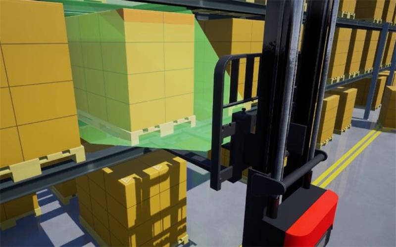
The first tip is understanding where ToF performs best. The chart below illustrates working distance vs. 3D accuracy. Our cameras are ideal for 0.1m–5m ranges with ~5mm error, making them unsuitable for high-detail 3D scanning (e.g., optical metrology). They excel in:
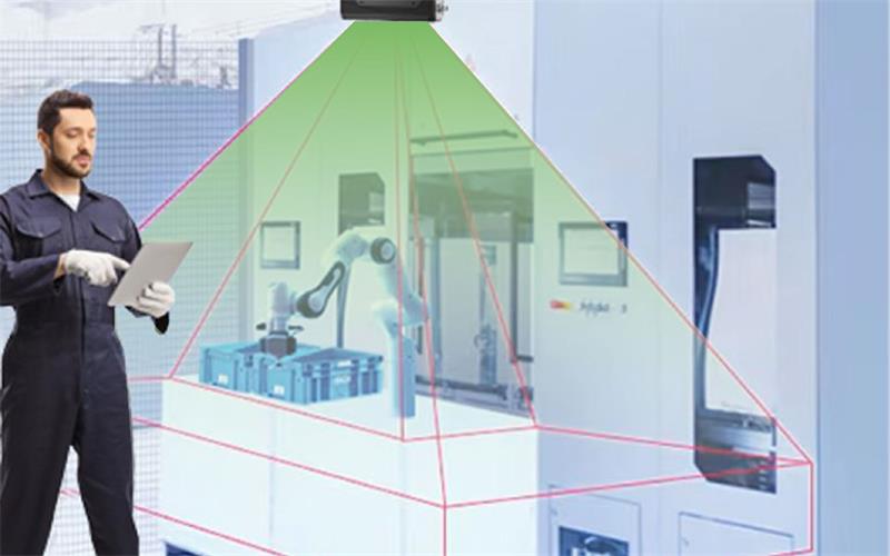
- Short-range robot navigation & obstacle avoidance
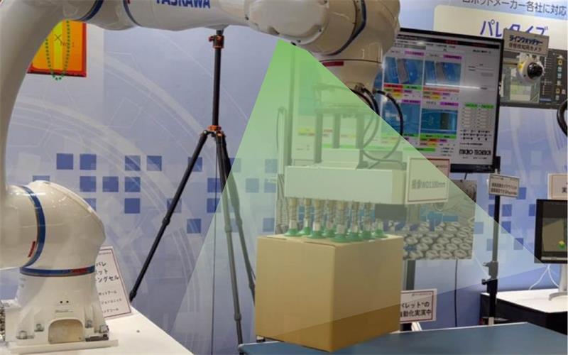
- Automated material handling (e.g., pallet stacking, bin picking)
VI. Lighting Conditions
How to optimize ToF performance? Start with Lighting.
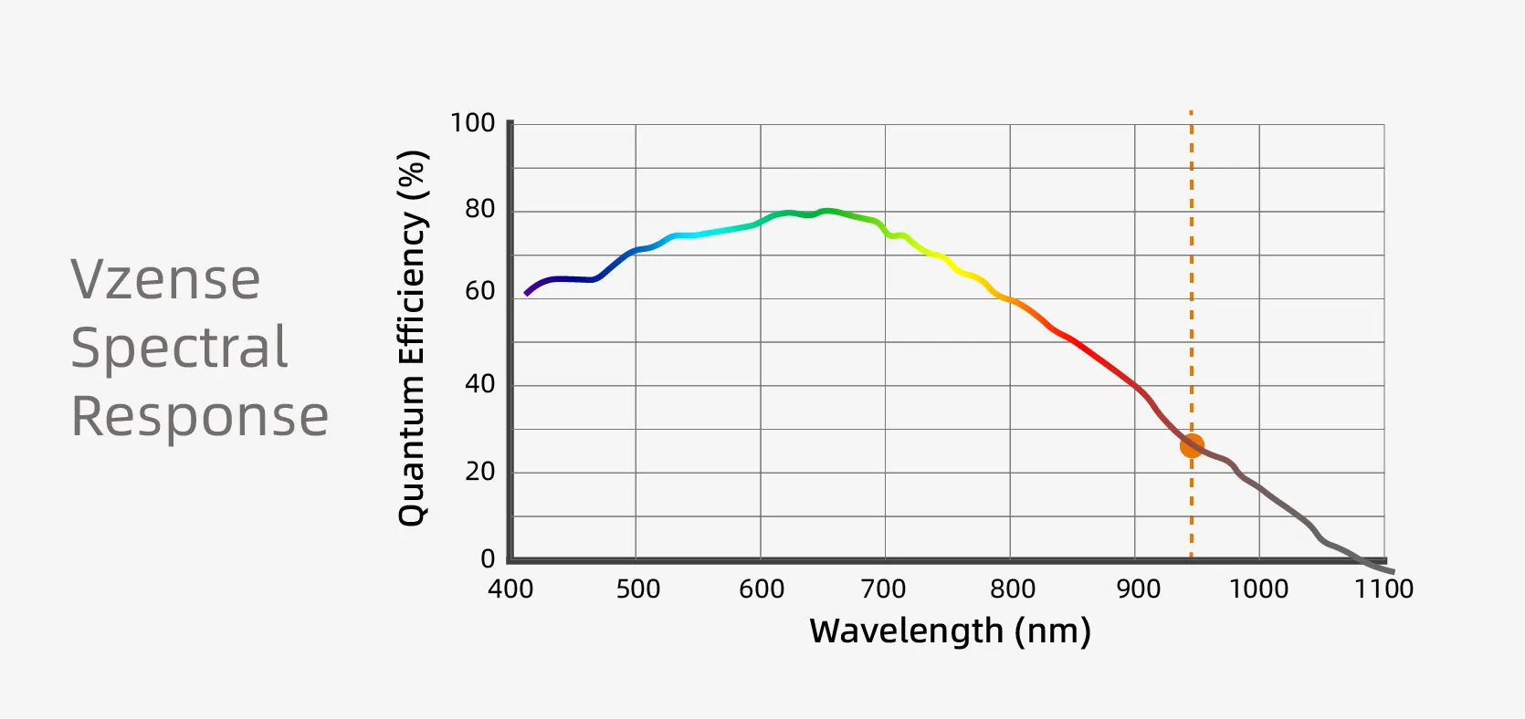
The spectral response curve highlights 940nm wavelength, chosen because sunlight naturally attenuates at this frequency. ToF cameras also use bandpass filters to block ambient interference.
Key Takeaway: For outdoor use, select a model with a 940nm emitter and bandpass filter.
VII. Motion Blur
In CW-iToF, a single depth frame comprises four 90°-phase-shifted subframes. Fast-moving objects or camera motion can cause 3D distortion. The motion tolerance depends on frame rate and exposure time.
Solution: Our P-iToF NYX series mitigates this with:
- High-duty-cycle pulses
- Lower SNR
- Shorter exposure & higher frame rates
VIII. High/Low Reflectivity Surfaces
Extreme reflectivity (e.g., tires with mixed surfaces) poses challenges. Tests show:
- Without HDR: Increasing exposure improves low-reflectivity point clouds but may overexpose high-reflectivity areas.
- With HDR (1000μs exposure): Both surfaces are well-captured without overexposure.
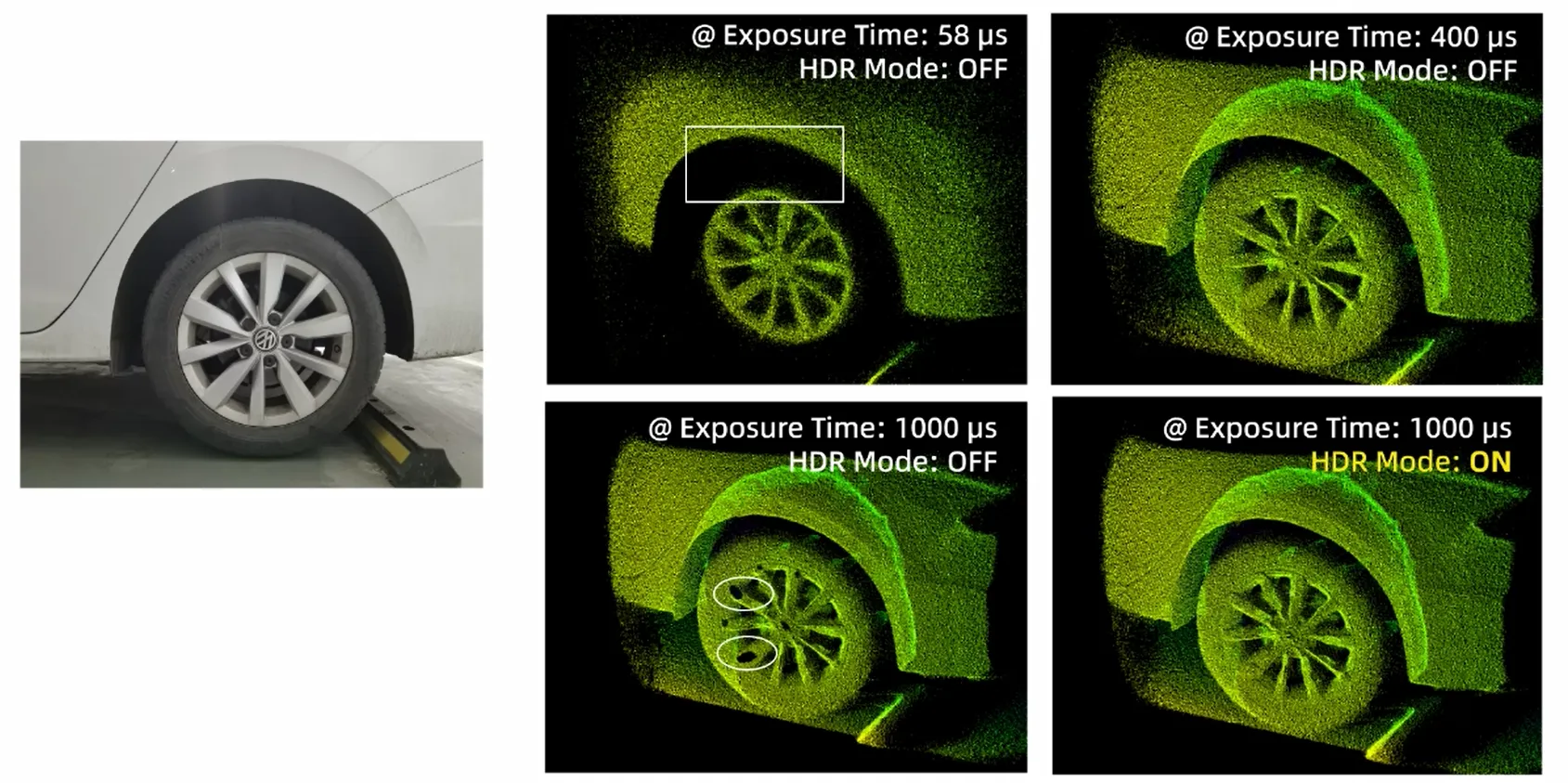
Recommendation: Adjust exposure + enable HDR for optimal results.
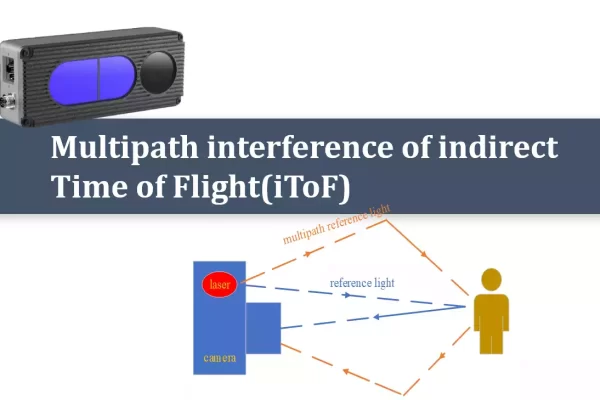
IX. Multipath Reflection
Multipath occurs when light reflects off multiple surfaces before returning, causing depth errors (e.g., missing corners in concave structures).
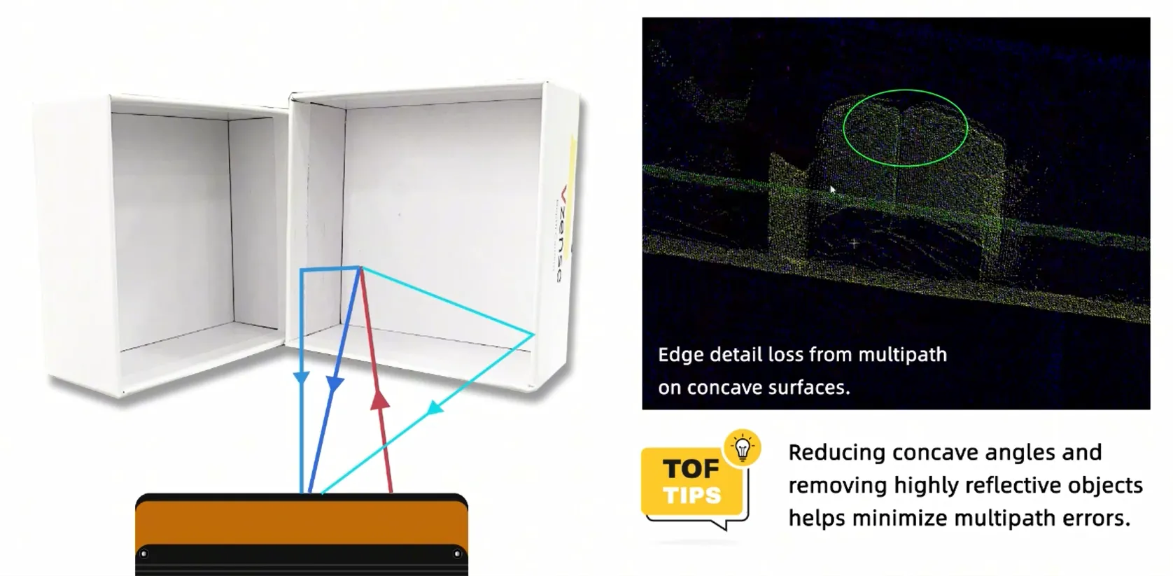
Mitigation: Minimize concave angles and remove unnecessary reflective objects.
X. Flying Pixels
Flying pixels are erroneous 3D points near depth discontinuities (e.g., object edges), where foreground/background light blends.
Solutions:
- Improve ambient lighting
- Remove high-reflectivity objects
- Apply flying-pixel filters
XI. Software Filters
Goertek’s ToF software includes:
- Confidence Filtering: Removes low-SNR pixels via amplitude thresholding.
- Spatial Filtering: Noise reduction via kernel-based convolution.
- Flying-Pixel Filtering: Edge-aware median filtering for depth jumps.
- Temporal Filtering: Multi-frame averaging to suppress random noise.
This concludes our discussion. For further details or inquiries, visit our website or leave a comment.