In industrial vision use cases, time synchronization is particularly important to ensure time consistency and accuracy between different devices. Clock synchronization protocols can be divided into two categories: hardware-based protocols and software-based protocols. Hardware-based protocols often rely on specialized hardware devices, such as the Global Positioning System (GPS) and IEEE 1588 Precision Time Protocol (PTP), to ensure clock synchronization. Such protocols generally have higher accuracy and stability because they can provide high-precision and high-resolution timers. However, such methods are often more expensive than software-based protocols. Software-based protocols enable clock synchronization through software running on a computer system, such as Network Time Protocol (NTP) and Clock Synchronization Protocol (TSP). These protocols are usually simple and suitable for common hardware devices.
Table of Contents
Introduction to NTP
Network Clock Protocol (NTP) is a UDP-based protocol that is used to synchronize the clocks of computer systems. It was created by David Mills in 1985 and has become a standard protocol widely used on the Internet. NTP uses a tree structure to achieve time synchronization. It is divided into two roles: the clock source provides the time standard, and the clock client synchronizes the local clock by communicating with the clock source, which is the most typical C/S mode. As shown in the figure below:
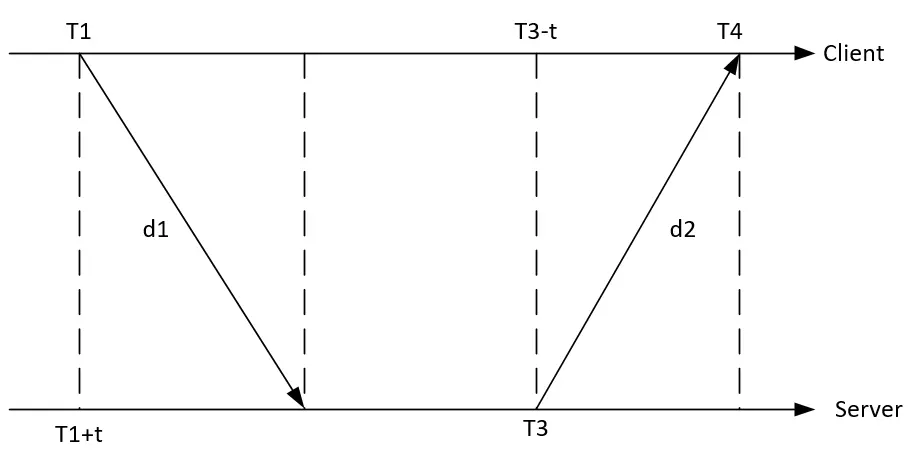
The client first sends an NTP packet to the server, which contains the timestamp T1 when the packet leaves the client, and when the server receives the packet, it fills in the timestamp T2 of the packet arrival and the timestamp T3 of the packet departure, and then immediately returns the packet to the client. When the client receives the response packet, it records the timestamp T4 returned by the packet. The client can calculate two key parameters using the above four time parameters: the round-trip delay d of the NTP packet and the clock deviation t between the client and the server. The client uses the clock skew to adjust the local clock so that its client and server times are consistent.
According to the calculation principle, the timing accuracy and reliability of NTP are affected by factors such as network delay and server performance, and the clock synchronization accuracy is limited, so NTP is also mainly used for timing or second-level synchronization.
Notes: In industrial vision scenarios, if the synchronization requirements are not high, you can use NTP to time alignment. Based on principle and experience, if the network is high-performance LAN and the performance of the NTP server is good, the synchronization accuracy of NTP should not exceed 10 ms.
NTP configuration method
NTP is used in the standard C/S mode, and the camera in use is used as the NTP client, so the NTP server needs to exist and be configured on the LAN.
NTP Server configuration
NTP Server exists in many different forms, such as Windows or Linux industrial computers, dedicated NTP servers, etc. Configure your server based on your specific requirements. In this article, Windows (Win10) and Linux (Ubuntu) are used as examples to build NTP servers.
Windows
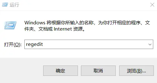
step1:win+r to open the run window, enter regedit, and click “OK“. As shown in the figure below:
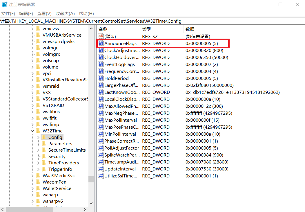
Modify the first registry value, Catalogue\HKEY_LOCAL_MACHINE\SYSTEM\CurrentControlSet\Services\W32Time\Config, AnnounceFlags change the value to 5. As shown in the figure below:
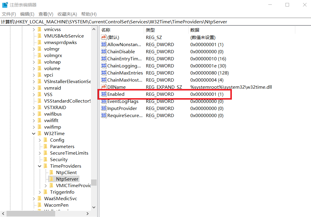
Modify the second registry value, Catalogue\HKEY_LOCAL_MACHINE\SYSTEM\CurrentControlSet\Services\W32Time\TimeProviders\NtpServer, Enabled change the value to 1. As shown in the figure below:
Run Windows powershell (Administrator) and run the following commands:
net stop w32time:service is stopping
net start w32tim:service is starting
w32tm /stripchart /computer:127.0.0.1:verify that the service has been started successfully
$ net stop w32time
The Windows Time service is stopping.
The Windows Time service was stopped successfully.

$ net start w32time
The Windows Time service is starting.
The Windows Time service was started successfully.

$ w32tm /stripchart /computer:127.0.0.1
tracking 127.0.0.1 [127.0.0.1:123]
The current time 2024/7/2 17:57:22
17:57:22, d:+00.0002855s o:+00.0000984s  [                           *                           ]
17:57:24, d:+00.0002224s o:+00.0000740s  [                           *                           ]
If the logs are printed separately as above, the settings are successful.
Linux
Use the command to install the ntp tool sntp.
$ sudo apt update
$ sudo apt install ntp -y
After the installation is complete, run the following command to ensure that the installation is successful:
$ sntp --version
sntp 4.2.8p10@1.3728-o (1)
After the installation is complete, the NTP service is started by default and can be viewed by running the following command:
$ service ntp status

● ntp.service - Network Time Service
   Loaded: loaded (/lib/systemd/system/ntp.service; enabled; vendor preset: enabled)
   Active: active (running) since Tue 2024-07-02 10:01:44 CST; 4h 31min ago
     Docs: man:ntpd(8)
 Main PID: 1975 (ntpd)
   CGroup: /system.slice/ntp.service
           └─1975 /usr/sbin/ntpd -p /var/run/ntpd.pid -g -u 116:122

Jul 02 10:01:47 firefly ntpd[1975]: Soliciting pool server 5.79.108.34
Jul 02 10:01:47 firefly ntpd[1975]: Soliciting pool server 202.118.1.81
Jul 02 10:01:48 firefly ntpd[1975]: Soliciting pool server 116.203.151.74
Jul 02 10:01:48 firefly ntpd[1975]: Soliciting pool server 78.46.102.180
Jul 02 10:01:49 firefly ntpd[1975]: Soliciting pool server 162.159.200.123
Jul 02 10:01:49 firefly ntpd[1975]: Soliciting pool server 139.199.215.251
Jul 02 10:01:49 firefly ntpd[1975]: Soliciting pool server 91.189.91.157
Jul 02 10:01:50 firefly ntpd[1975]: Soliciting pool server 2a01:4f8:c2c:477d::2
Jul 02 10:21:06 firefly ntpd[1975]: 116.203.151.74 local addr 192.168.100.105 -> <null>
Jul 02 10:21:58 firefly ntpd[1975]: 78.46.102.180 local addr 192.168.100.105 -> <null>
The above completes the configuration of NTP Server.
NTP Client configuration
PC Client
After the NTP Server is set up, you can use another PC in the same LAN as a client for simple verification. Let’s take Linux as an example:
Install the ntpdate tool
$ sudo apt install ntpdateIn order for the client system to resolve the NTP server by hostname, you need to add the IP address and hostname file of the NTP server to /etc/hosts.
$ sudo vim /etc/hostsAdd the following content to the hosts file:
192.168.1.122   ntp-test-server #linux NTP Server
192.168.1.106   ntp-test-win10 # windows NTP Server
192.168.1.122: IP Address of NTP Server in LAN
ntp-test-server:Server alias
To check if the client system is in time synchronization with the NTP server, run the following command.
$ sudo ntpdate ntp-test-server
2 Jul 15:13:38 ntpdate[2603]: adjust time server 192.168.1.122 offset -0.051502 sec
$ sudo ntpdate ntp-test-win10
2 Jul 17:58:08 ntpdate[2733]: adjust time server 192.168.1.106 offset 0.000001 sec
The above describes the synchronization success of the log, and the offset is the time difference between the local time and the server time during the synchronization.
Notes: You can use this method to verify the offset value during synchronization for multiple times in a row, if the offset value is consistently large, it means that the network connection or NTP server performance is not good. However, this value does not represent the NTP synchronization time accuracy.
Vzense Camera
If you want to use a camera that supports NTP Client (please refer to the data sheet for a specific model that supports NTP).
Method 1: Setting with ScepterGUITool
open “ScepterGUITool“, search for and connect the camera. After the connection is successful, open the “Network” page. Select “NTP” Enable, enter the LAN address of the NTP server, and click “Set” to set successfully.As shown in the figure below:
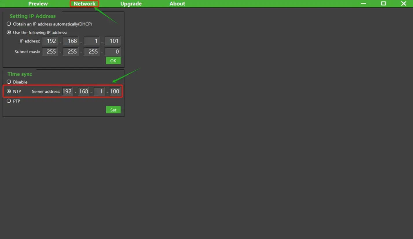
Method 2: Setting with software API
Sample code:
BaseSDK/Windows/Samples/Base/NYX650/DeviceSetNTP.
Struct Type:
typedef struct
{
    uint8_t flag;     //!< 0: disable, 1: NTP, 2: PTP, only NTP needs the ip.
    uint8_t ip[16];   //!< just for NTP.
} ScTimeSyncConfig;
The LAN address of the NTP server can be set or obtained by below API:
//Set the parameters for enable the NTP time sync
ScStatus scSetRealTimeSyncConfig(ScDeviceHandle device, ScTimeSyncConfig params);
//Get the parameters for the status of NTP time sync
ScStatus scGetRealTimeSyncConfig(ScDeviceHandle device, ScTimeSyncConfig* pParams);
Notes:
1) The camera supports NTP’s real-time setting enabled, which can take effect immediately. After the setting is successful, the camera will also record and enable this function, and it will still be used by default the next time the camera is powered on.
2) If the setup fails, please check whether the camera model you are using supports the NTP function, and if so, contact FAE to confirm whether the current firmware version supports it.
Verification method
After the camera is successfully set, the synchronization and timing function of NTP is enabled by default when the camera is turned on, and in order to ensure the continuous accuracy of the time, it will be synchronized with the server at an interval of 5s.
How do I know if the camera has been successfully synchronized with the NTP server? Verification can be checked by printing the timestamp of the acquired image.
typedef struct
{
    uint32_t      frameIndex;        //The index of the frame.
    ScFrameType   frameType;         //The type of frame. See ::ScFrameType for more information.
    ScPixelFormat pixelFormat;       /*The pixel format used by a frame. See ::ScPixelFormat for more
                                       information.*/
    uint8_t*      pFrameData;        //A buffer containing the frame’s image data.
    uint32_t      dataLen;           //The length of pFrame, in bytes.
    uint16_t      width;             //The width of the frame, in pixels.
    uint16_t      height;            //The height of the frame, in pixels.
    uint64_t      deviceTimestamp;   /*The timestamp(in milliseconds) when the frame be generated on the
                                       device. Frame processing and transfer time are not included.*/
} ScFrame;
Include a deviceTimestamp member in the struct of the image acquisition with a UNIX timestamp of uint64.
The code for adding the print timestamp to the drawing routine of samples is as follows:
BaseSDK/Windows/Samples/Base/NYX650/FrameCaptureAndSave.
//1.ReadNextFrame.
//2.GetFrame acoording to Ready flag and Frametype.
for(int i = 0;i < frameSpace;i++)
{
    status = scGetFrameReady(deviceHandle, 1200, &FrameReady);
    if (status != ScStatus::SC_OK)
    {
        cout << "scGetFrameReady failed status:" <<status<< endl;
        continue;
    }
    //depthFrame for example.
    if(1 == FrameReady.depth)
    {
        status = scGetFrame(deviceHandle, SC_DEPTH_FRAME, &depthFrame);
        if (depthFrame.pFrameData != NULL)
        {
            cout << "get Frame successful,status:" << status << "  ";
            cout << "deviceTimestamp:" << depthFrame.deviceTimestamp <<  endl;
        }
    }
}
When the code is executed, the deviceTimestamp value will be printed when the graph is successfully retrieved.
If NTP synchronization is not set, or if the synchronization is not successful after the camera is powered off and powered on, the following logs are printed:
---FrameCaptureAndSave---
Get device count: 1
serialNumber:GN6501CBCA3310168
ip:192.168.1.102
connectStatus:1
get Frame successful,status:0  deviceTimestamp:18224
get Frame successful,status:0  deviceTimestamp:18257
get Frame successful,status:0  deviceTimestamp:18291
get Frame successful,status:0  deviceTimestamp:18324
get Frame successful,status:0  deviceTimestamp:18357
get Frame successful,status:0  deviceTimestamp:18391
get Frame successful,status:0  deviceTimestamp:18424
get Frame successful,status:0  deviceTimestamp:18457
get Frame successful,status:0  deviceTimestamp:18491
get Frame successful,status:0  deviceTimestamp:18524
get Frame successful,status:0  deviceTimestamp:18557
get Frame successful,status:0  deviceTimestamp:18591
get Frame successful,status:0  deviceTimestamp:18624
get Frame successful,status:0  deviceTimestamp:18657
get Frame successful,status:0  deviceTimestamp:18691
get Frame successful,status:0  deviceTimestamp:18724
get Frame successful,status:0  deviceTimestamp:18757
get Frame successful,status:0  deviceTimestamp:18791
get Frame successful,status:0  deviceTimestamp:18824
get Frame successful,status:0  deviceTimestamp:18857
---end---
After NTP synchronization is configured, the printed log is as follows:
---FrameCaptureAndSave---
Get device count: 1
serialNumber:GN6501CBCA3310168
ip:192.168.1.102
connectStatus:1
get Frame successful,status:0  deviceTimestamp:1719910682528
get Frame successful,status:0  deviceTimestamp:1719910682562
get Frame successful,status:0  deviceTimestamp:1719910682595
get Frame successful,status:0  deviceTimestamp:1719910682629
get Frame successful,status:0  deviceTimestamp:1719910682662
get Frame successful,status:0  deviceTimestamp:1719910682695
get Frame successful,status:0  deviceTimestamp:1719910682728
get Frame successful,status:0  deviceTimestamp:1719910682762
get Frame successful,status:0  deviceTimestamp:1719910682795
get Frame successful,status:0  deviceTimestamp:1719910682828
get Frame successful,status:0  deviceTimestamp:1719910682862
get Frame successful,status:0  deviceTimestamp:1719910682895
get Frame successful,status:0  deviceTimestamp:1719910682928
get Frame successful,status:0  deviceTimestamp:1719910682962
get Frame successful,status:0  deviceTimestamp:1719910682995
get Frame successful,status:0  deviceTimestamp:1719910683029
get Frame successful,status:0  deviceTimestamp:1719910683062
get Frame successful,status:0  deviceTimestamp:1719910683096
get Frame successful,status:0  deviceTimestamp:1719910683129
get Frame successful,status:0  deviceTimestamp:1719910683162
---end---
There will be a significant difference in the timestamp printing value, because the default start timestamp used by the camera is 0, and after the NTP time is synchronized, it will be changed to the system time of the NTP server.
Further confirmation can also be done through RTC time conversion, the reference code is as follows:
#include <time.h> //Reference c library functions

/*
Omit part of code
*/

if (depthFrame.pFrameData != NULL)
{
    struct tm *p;
    time_t t;
    char s[100];
    cout << "get Frame successful,status:" << status << "  ";
    t = depthFrame.deviceTimestamp/1000;
    p = gmtime(&t);
    strftime(s, sizeof(s), "%Y-%m-%d %H:%M:%S", p);
    printf("%d: %s\n", (int)t, s);
}
After the run is successful, print the log:
---FrameCaptureAndSave---
Get device count: 1
serialNumber:GN6501CBCA3310168
ip:192.168.1.102
connectStatus:1
get Frame successful,status:0  1719911020: 2024-07-02 09:03:40
get Frame successful,status:0  1719911020: 2024-07-02 09:03:40
get Frame successful,status:0  1719911021: 2024-07-02 09:03:41
get Frame successful,status:0  1719911021: 2024-07-02 09:03:41
get Frame successful,status:0  1719911021: 2024-07-02 09:03:41
get Frame successful,status:0  1719911021: 2024-07-02 09:03:41
get Frame successful,status:0  1719911021: 2024-07-02 09:03:41
get Frame successful,status:0  1719911021: 2024-07-02 09:03:41
get Frame successful,status:0  1719911021: 2024-07-02 09:03:41
get Frame successful,status:0  1719911021: 2024-07-02 09:03:41
get Frame successful,status:0  1719911021: 2024-07-02 09:03:41
get Frame successful,status:0  1719911021: 2024-07-02 09:03:41
get Frame successful,status:0  1719911021: 2024-07-02 09:03:41
get Frame successful,status:0  1719911021: 2024-07-02 09:03:41
get Frame successful,status:0  1719911021: 2024-07-02 09:03:41
get Frame successful,status:0  1719911021: 2024-07-02 09:03:41
get Frame successful,status:0  1719911021: 2024-07-02 09:03:41
get Frame successful,status:0  1719911021: 2024-07-02 09:03:41
get Frame successful,status:0  1719911021: 2024-07-02 09:03:41
get Frame successful,status:0  1719911021: 2024-07-02 09:03:41
---end---Notes:
1) The timestamp in the device is the moment when the image is generated, and does not include the delay of image processing and network transmission.
2) The timestamp used by the device is UTC time.
There is no RTC module in the camera, so it needs to be resynchronized with the master clock after each power-up. There is a time difference between the power start of the camera and the successful time synchronization, which will vary according to the network conditions (about 17s in normal scene), so if the host computer reads the image earlier, the timestamp of the image in the first few seconds will not be synchronized successfully.


