Table of Contents
Exposure time of 3D ToF camera
The camera principle of ToF is to measure the distance by emitting a laser that reflects off the surface of an object and returns, as shown in the image below:

Several factors can affect the strength of the reflected signal including the distance to the target object, the reflectivity of the target object, and the time of the laser is emitted (i.e. exposure time). Among these, exposure time is the only factor that can be autonomously adjusted by the camera. Choosing the appropriate exposure time for the application scenario is very important, as it directly affects parameters such as accuracy, precision, and distance range.

If the exposure time is too short, the signal strength will weaken, resulting in a lower signal-to-noise ratio(SNR), poorer accuracy and precision, and even failing to measure distant objects or low-reflectivity objects, creating a long-distance blind spot.
If the exposure time is too long, the signal strength will increase, which is beneficial for improving the SNR, accuracy, precision, and measurement range. However, for highly reflective objects, especially those at near range, there is a risk of pixel saturated, creating a near-distance blind spot. As shown in the image below, the red outline marked area pixels are saturated due to the strong signal, resulting in missing depth information.
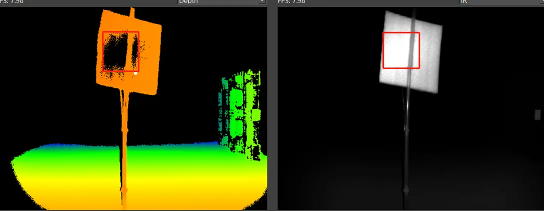
Generally, to achieve greater distances or more stable point cloud quality without causing overexposure (sautration), it is necessary to increase the exposure time (Te) of the ToF camera. However, increasing the exposure time will lengthen the time required for depth map of a frame, thereby reducing the frame rate.
The short/long exposure time of a frame composition is shown below:
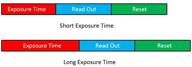
Correspondingly, if we need to achieve a higher exposure time, we must firstly lower the frame rate;
For example, with the NYX650, when trying to capture a standing black tray (reflectivity less than 5%) at a distance of 2 meters from the camera. As shown in the image below:
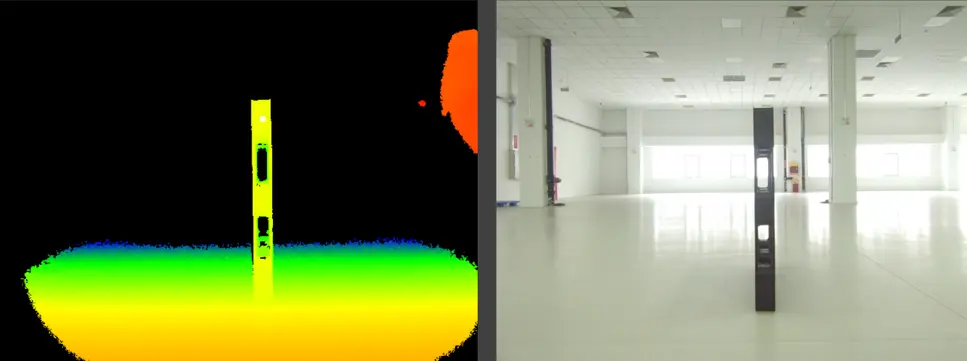
When the frame rate is set to 30fps, the maximum exposure time is 7300µs. At this setting, the point cloud of the pallet shows significant jitter and many flying pixels. As shown in the image below:
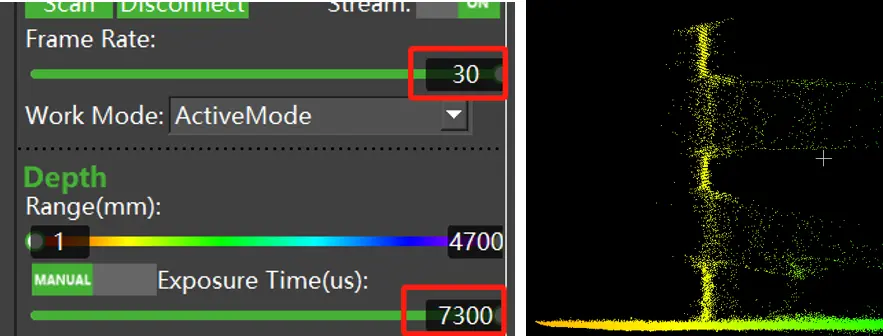
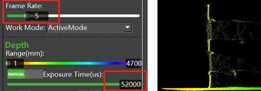
Reducing the frame rate to 5fps increases the maximum exposure time to 52000µs. Compared to the 30fps and 7300µs setting, the point cloud of the pallet shows significantly less jitter and fewer flying pixels. As shown in the image below:
At active mode, frame rate refers to the real-time frame counts in one second repetively.
While at trigger mode (both hardware trigger and software trigger), frame rate refers to the maximum frame rate the trigger signal frequency can be. For example, if the frame rate is set to 10fps at hardware trigger mode, so the minimum time interval between two adjacent trigger signal must be longer than 1/10s.
Software API for exposure time and frame rate adjustment
Sample code:
BaseSDK/Windows/Samples/Base/NYX650/ToFExposureTimeSetGet.
Struct Type:
/**
 * @brief    Specifies the type of sensor.
 */
typedef enum
{
    SC_TOF_SENSOR   = 0x01,   //ToF camera.
    SC_COLOR_SENSOR = 0x02,   //RGB camera.
} ScSensorType;
/**
* @brief Exposure control mode.
*/
typedef enum
{
SC_EXPOSURE_CONTROL_MODE_AUTO = 0, //Enter the auto exposure mode.
SC_EXPOSURE_CONTROL_MODE_MANUAL = 1, //Enter the manual exposure mode.
} ScExposureControlMode;The maximum exposure time can be obtained by below API:
//for ToF sensor, input the sensorType is SC_TOF_SENSOR, it can get the maximum exposure time of ToF sensor at the current frame rate
ScStatus scGetMaxExposureTime(ScDeviceHandle device, ScSensorType sensorType, int32_t* pMaxExposureTime);
The exposure mode (auto or manual) can be set or obtained by below API:
//set the exposure control mode, AEC or manual, for ToF sensor, input the sensorType is SC_TOF_SENSOR
ScStatus scSetExposureControlMode(ScDeviceHandle device, ScSensorType sensorType, ScExposureControlMode controlMode);

//get the current exposure control mode, AEC or manual, for ToF sensor, input the sensorType is SC_TOF_SENSOR
ScStatus scGetExposureControlMode(ScDeviceHandle device, ScSensorType sensorType, ScExposureControlMode* pControlMode)
The real-time exposure time can be set and obtained by below API:
//set the exposure time of manual mode, for ToF, input sensorType is SC_TOF_SENSOR
ScStatus scSetExposureTime(ScDeviceHandle device, ScSensorType sensorType, int32_t exposureTime)

//get the current exposure time of manual mode, for ToF, input sensorType is SC_TOF_SENSOR
ScStatus scGetExposureTime(ScDeviceHandle device, ScSensorType sensorType, int32_t* pExposureTime)
The frame rate can be set and obtained by below API:
// value means the expected frame rate
ScStatus scSetFrameRate(ScDeviceHandle device, int32_t value)

//returned pValue means the current frame rate
ScStatus scGetFrameRate(ScDeviceHandle device, int32_t* pValue)
FAQ
How to improve the recognition of low reflectivity objects?
a. Increase exposure time.
As shown in the previous example, increasing the exposure time can improve the point cloud effect. However, it is essential to avoid overexposure and stray light issues caused by excessive exposure time.
b. Lower the confidence filter threshold.
Reducing the threshold of the confidence filter can improve the recognition of low reflectivity objects. However, note that this method does not increase signal strength and may introduce other noise.
How to choose the appropriate exposure time?
Generally, under the premise of avoiding overexposure, selecting an appropriate frame rate to achieve a longer exposure time can significantly improve the effect.
How to handle scenes with both high and low reflectivity objects?
If the scene requires measuring both high and low reflectivity objects, the low reflectivity objects will need a longer exposure time to achieve higher image quality. However, this will cause exposure saturate for high reflectivity objects. In this case, using HDR (High Dynamic Range) can improve the situation. For more details, please refer to the technology note “TN05-Understanding High Dynamic Range (HDR) mode of indirect Time-of-Flight (iToF)“.


