Table of Contents
Basic principle
Vzense 3D cameras are equipped with RGB color image sensors and depth image ToF sensors. Image alignment refers to the process of finding the same object in the world coordinate system within the images from both RGB color image sensors and depth image sensors through coordinate transformation.
As shown in the schematic diagram below, due to the different physical locations and optical parameters of the color image sensors and depth image sensors, the same object captured by both sensors will result in different corresponding pixel points in each sensor’s pixel coordinate system due to parallax. Therefore, it is necessary to find a spatial transformation relationship and establish a unified coordinate system to map one image onto another so that the pixel data in the two images correspond one-to-one.
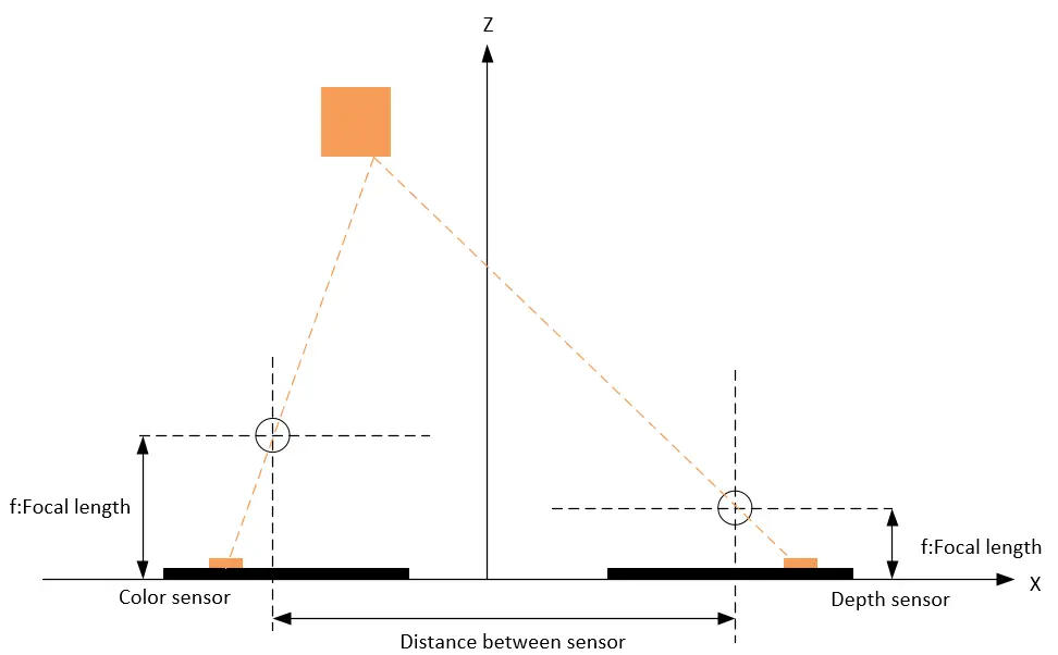
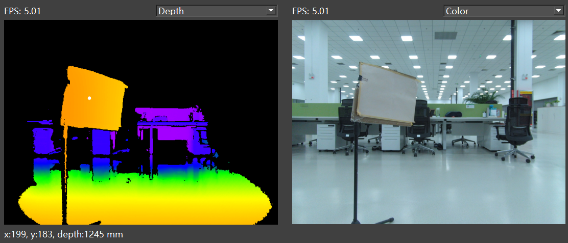
Definition of coordinate systems and detailed camera parameters in machine vision systems
For further details, please refer to “TN08-Machine vision system coordinate systems and parameters of camera“.
Types and methods of alignment
Based on the above principles, Vzense products have designed two types of image alignment methods:
1. Align depth image to color image.
2. Align color image to depth image.
Align depth image to color image
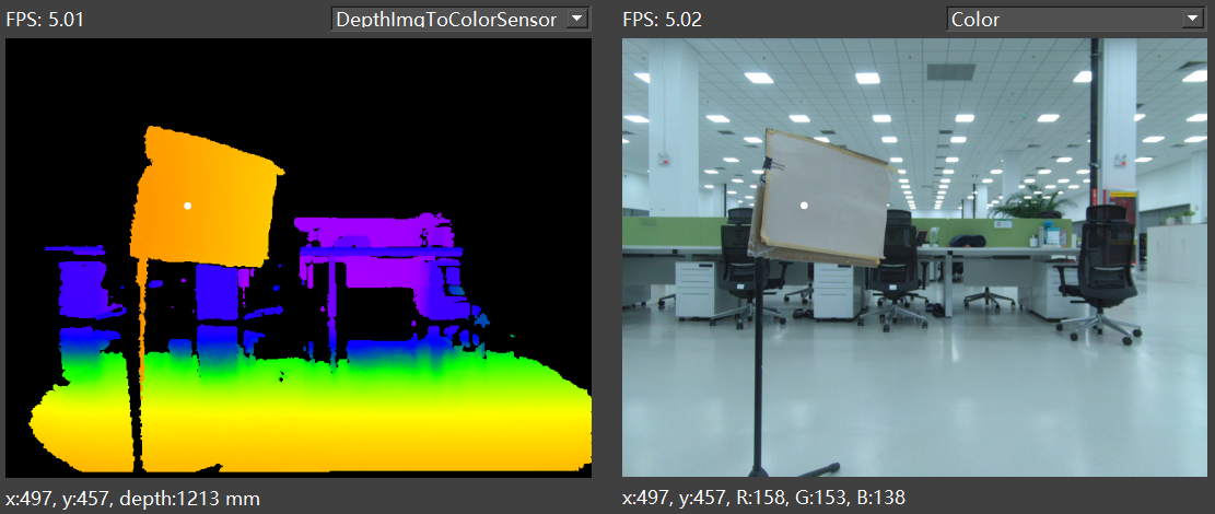
This method uses the color image as the unified coordinate system, aligning the depth image to the color image coordinate system, making each color pixel in the color image contain depth values. As below figure shows:
Usage scenario:
Aligning the depth image to the color image is a commonly used method. For example, in target detection scenarios, algorithms typically use the color image for deep learning model target detection, then obtain the target box or segmented point set in the color image. Finally, the aligned depth image is used to get the distance values of the corresponding points for 3D information calculation and positioning.
Implementation in ScepterGUITool:
In the depth image preview window, select “DepthImgToColorSensor” to enable the alignment of the depth image to the color image. As below figure shows:
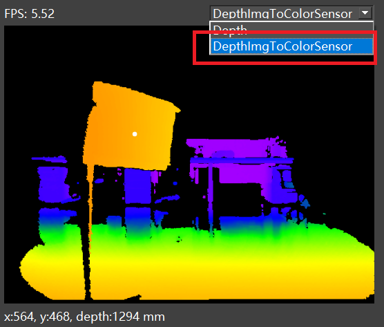
After enabling, left-clicking within the depth/color image will display the aligned point information.
Related software API in SDK:
Sample code:
BaseSDK/Windows/Samples/Base/NYX650/TransformDepthImgToColorSensorFrame.
The alignment feature is disabled by default. To use it, you need to enable it through the following API calls.
//Set enables the alignment of Depth images to color images
ScStatus scSetTransformDepthImgToColorSensorEnabled(ScDeviceHandle device, bool bEnabled);

//Gets whether alignment of Depth image to color image is enabled
ScStatus scGetTransformDepthImgToColorSensorEnabled(ScDeviceHandle device, bool* bEnabled);

//Get Frame
status = scGetFrameReady(deviceHandle, 1200, &FrameReady);
if (1 == FrameReady.transformedDepth)
{
    status = scGetFrame(deviceHandle, SC_TRANSFORM_DEPTH_IMG_TO_COLOR_SENSOR_FRAME, &frame);
}
Align color image to depth image
This method uses the depth image as the unified coordinate system, aligning the color image to the depth image coordinate system, making each depth pixel in the depth image contain color information. As below figure shows:
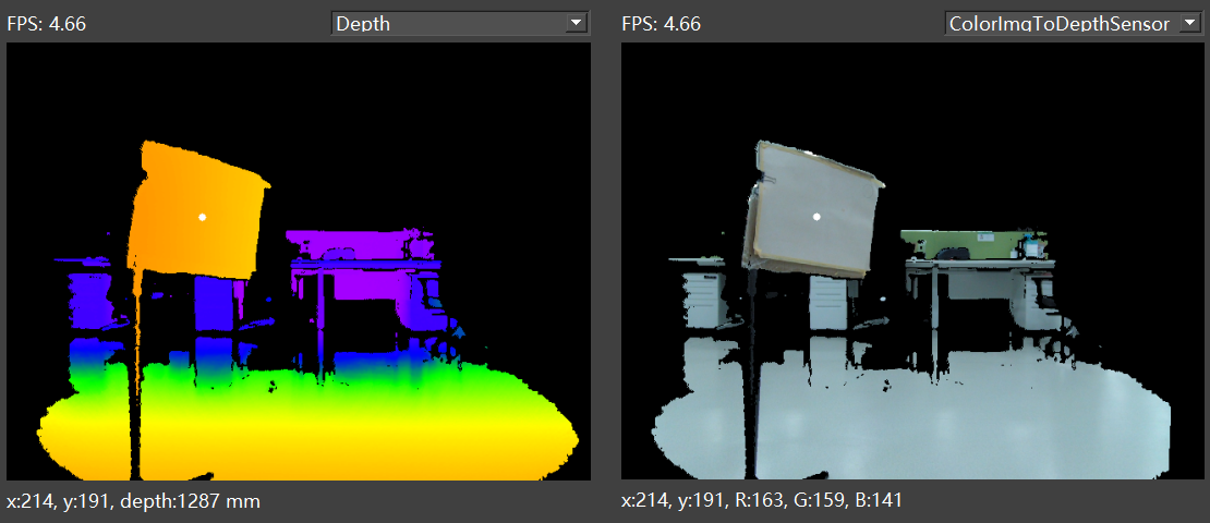
Usage scenario:
Aligning the color image to the depth image is suitable for scenarios where algorithms primarily use the depth image and then acquire color information. For example, in volume detection scenarios, the algorithm calculates the volume of an object using the depth image and then draws the target box in the color image for preview after acquiring the aligned color object positions.
This method is also applicable when using the distance information from the depth image for ROI segmentation, and then using the aligned color image for semantic recognition, reducing computational requirements.
Implementation in ScepterGUITool:
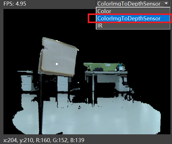
In the color image preview window, select “ColorImgToDepthSensor” to enable the alignment of the color image to the depth image. As below figure shows:
Related software API in SDK:
Sample code:
BaseSDK/Windows/Samples/Base/NYX650/TransformColorImgToDepthSensorFrame.
The alignment feature is disabled by default. To use it, you need to enable it through the following API calls.
//Set the enable switch
ScStatus scSetTransformColorImgToDepthSensorEnabled(ScDeviceHandle device, bool bEnabled);

//Gets whether alignment is enabled
ScStatus scGetTransformColorImgToDepthSensorEnabled(ScDeviceHandle device, bool* bEnabled);

//Get Frame
status = scGetFrameReady(deviceHandle, 1200, &FrameReady);
if (1 == FrameReady.transformedColor)
{
    status = scGetFrame(deviceHandle, SC_TRANSFORM_COLOR_IMG_TO_DEPTH_SENSOR_FRAME, &frame);
}
How to obtain camera intrinsic and extrinsic parameters?
You can obtain the intrinsic and extrinsic parameters of the camera using the software APIs below. You can choose to obtain the intrinsic parameters for the ToF senor or the RGB sensor based on the parameter selection.
Sample code:
BaseSDK/Windows/Samples/Base/NYX650/DeviceParamSetGet.
//Get sensor intrinsic parameters according to the sensor type
ScStatus scGetSensorIntrinsicParameters(ScDeviceHandle device, ScSensorType sensorType, ScSensorIntrinsicParameters* pSensorIntrinsicParameters);

//Get sensor extrinsic parameters according to the sensor type
ScStatus scGetSensorExtrinsicParameters(ScDeviceHandle device, ScSensorExtrinsicParameters* pSensorExtrinsicParameters);Note: When converting the point cloud or aligning to the world coordinate system using intrinsic parameters, you should choose the appropriate intrinsic parameters based on the alignment method:
If not aligned, use the intrinsic parameters of the ToF camera.
If using the method of aligning depth images to color images, use the intrinsic parameters of the RGB camera.
If using the method of aligning color images to depth images, use the intrinsic parameters of the ToF camera.
How to convert depth images to point clouds?
It is recommended that users use our SDK API to achieve depth image conversion to point clouds. According to user needs, we provide several methods for converting point clouds:
(1) Conversion of the entire image: The software API for converting the entire image is as follows:
Sample code:
BaseSDK/Windows/Samples/Base/NYX650/PointCloudCaptureAndSave.
//From depth frame to point cloud
ScStatus scConvertDepthFrameToPointCloudVector(ScDeviceHandle device, const ScFrame* pDepthFrame, ScVector3f* pWorldVector);
(2) Partial depth pixel conversion: To reduce processor consumption, customers can convert only part of the depth image pixels to point clouds using the following software API.
Sample code:
BaseSDK/Windows/Samples/Base/NYX650/PointCloudVectorAndSave.
//From depth frame point to point cloud point
ScStatus scConvertDepthToPointCloud(ScDeviceHandle device, ScDepthVector3* pDepthVector, ScVector3f* pWorldVector, int32_t pointCount, ScSensorIntrinsicParameters* pSensorParam);Note: Select the correct intrinsic parameters according to the alignment method:
If not aligned, use the intrinsic parameters of the ToF camera.
If using the method of aligning depth images to color images, use the intrinsic parameters of the RGB camera.
If using the method of aligning color images to depth images, use the intrinsic parameters of the ToF camera.


