The Goermicro 3D depth camera uses ToF camera technology for distance measurement. During operation, the camera emits infrared light, which reflects off objects and returns to the sensor. The camera calculates the distance to the object by measuring the time difference between the emission and return of the light.
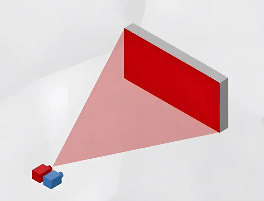
Since the measurement process requires active infrared light emission, multiple 3D cameras working in the same scene (with overlapping fields of view) may interfere with each other. This interference can cause significant errors in depth measurement, severely degrading depth quality and limiting the application of ToF cameras. To address this issue, we provide a method for multi-camera coexistence.
Table of Contents
The work timing of the 3D camera
Each working cycle of the camera involves infrared light emission and collection, and the calculation of distance values for each pixel. The number of measurements per second is called the frame rate. Each working cycle can be divided into two stages: exposure (laser emission and collection) and transmission. When multiple cameras work simultaneously, if their exposure stages overlap, camera A may receive the laser emitted by camera B, causing interference. The result is shown as follows:

Achieve multiple camera coexistence by trigger mode
Goermicro 3D Time of Flight cameras support slave trigger mode (hardware trigger mode and software trigger mode). In this mode, the camera waits for a trigger signal before starting a frame’s exposure and transmission. Each signal triggers only one exposure and transmission.
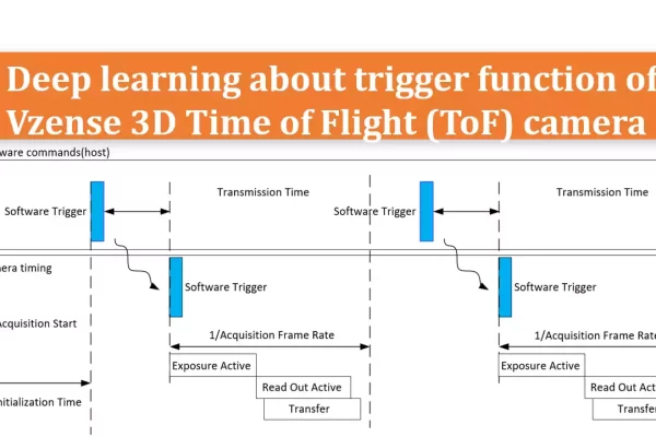
There are two types of triggers: hardware trigger and software trigger. A hardware trigger is driven by an external trigger source, and the camera starts image exposure immediately upon receiving a valid signal. A software trigger, unlike a hardware trigger, does not require an external trigger source and can trigger an image capture by calling an API. For more details, please refer to the application note “AN07-Deep learning about trigger function of Goermicro 3D Time of Flight (ToF) camera“.
Based on the ToF principle and the slave trigger mode provided by Goermicro, our ToF product series can achieve multi-camera coexistence through coordinated control. Coordinated control involves setting all cameras to trigger mode, with the master control platform controlling the exposure start time of different cameras to ensure they do not interfere with each other. Once in trigger mode, the camera will only work for one cycle upon receiving a trigger signal, allowing flexible control of different cameras’ image output times and frame rates as needed. However, this method requires balancing the frame rate and the number of cameras.

Suitable scenarios: When the camera’s working at a low frame rate, multiple cameras can be controlled by a single host or hardware trigger signal source.
How to use:
1. Hardware trigger:
Depending on the model of the camera you selected, refer to the specification to find the Ext_Trigger signal pin. Connect the corresponding trigger signals to the trigger pins of camera A, B, and C, respectively.

2. Software trigger:
Set all cameras A, B, and C to software trigger mode. Wait for the trigger signal.
Sample code:
BaseSDK/Windows/Samples/Base/NYX650/DeviceSWTriggerMode.
The API interface is:
//Set the working mode of the camera, inputing scworkmode is software trigger mode.
ScStatus scSetWorkMode(ScDeviceHandle device, ScWorkMode mode);

//Get the working mode of the camera.
ScStatus scGetWorkMode(ScDeviceHandle device, ScWorkMode* pMode);/**
* @brief The working mode of the camera.
*/
typedef enum
{
SC_ACTIVE_MODE = 0x00, //active mode or free running mode
SC_HARDWARE_TRIGGER_MODE = 0x01, //hardware trigger mode
SC_SOFTWARE_TRIGGER_MODE = 0x02, //software trigger mode
} ScWorkMode; Because the exposure time of each camera is probably different, it is recommended that the trigger signal interval of the adjacent camera is bigger than or equal to one working cycle. For example, taking 15fps as an example, after the trigger signal of camera A is issued, the trigger signal of camera B will be delayed for more than 66.7ms.
Unique adaptive multi-camera coexistence of the NYX series products
In some scenarios, multiple 3D ToF cameras are connected to different hosts without a synchronization mechanism, making coordinated control impossible. Typical scenarios include AGV/AMR, where ToF cameras are installed on different AGVs and move randomly with them, lacking a synchronized clock source. In this case, multi-camera coexistence cannot be achieved through trigger mode.
The NYX series ToF cameras have a unique multi-camera coexistence feature. They can automatically sense and avoid the laser signals of surrounding NYX series ToF cameras through built-in algorithms, achieving multi-camera coexistence for up to a dozen devices without any connection. As shown in the following picture:
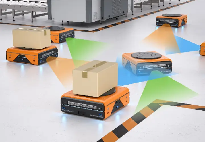
This method is very flexible and requires no user configuration and any physical connection. However, it should be noted that NYX series products can only recognize the laser signals of NYX series products and cannot avoid interference from other light sources.


