Table of Contents
What are the operating modes of the Vzense 3D ToF camera?
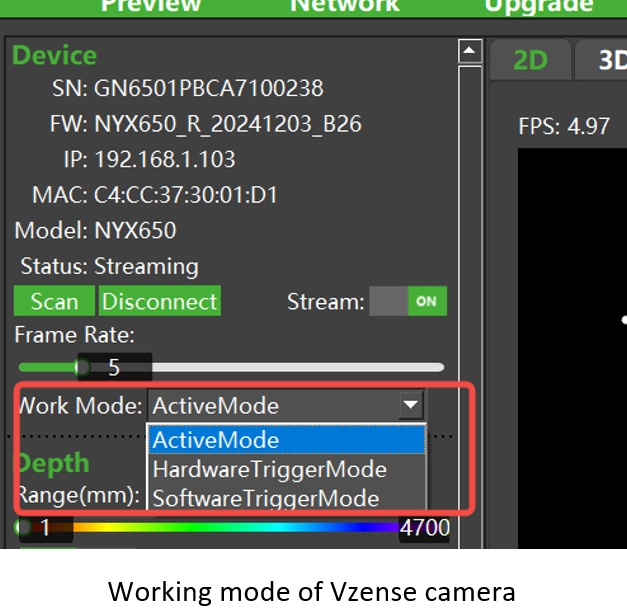
The Vzense 3D ToF camera provide three operating modes: Active、Hardware Trigger and Software Trigger.
1. Active
In active mode, the camera is in continuous streaming mode or free running mode. You can view the real-time image information captured by the camera by opening Stream “ON” in ScepterGUITool.
2. Hardware Trigger
In the hardware trigger mode, the external trigger source sends a trigger signal to the hardware trigger pin(WHITE pin) of the ToF camera to control the camera to start the acquisition of a frame. Each signal triggers only one exposure and transmission.
3. Software Trigger
In software trigger mode, the host controls the camera to start the acquisition of a frame by sending a software command to the ToF camera. Each software trigger command only cause one frame exposure and transmission.
As shown in the following figure, you can select the desired operating mode in ScepterGUITool according to your needs. As shown in the diagram below:
User can configure the working mode of ToF camera by below software API:
//Set the working mode of the camera, inputing scworkmode is hardware trigger mode.
ScStatus scSetWorkMode(ScDeviceHandle device, ScWorkMode mode);

//Get the working mode of the camera.
ScStatus scGetWorkMode(ScDeviceHandle device, ScWorkMode* pMode);/**
* @brief Different the working mode of the camera.
*/
typedef enum
{
SC_ACTIVE_MODE = 0x00, //active mode or free running mode
SC_HARDWARE_TRIGGER_MODE = 0x01, //hardware trigger mode
SC_SOFTWARE_TRIGGER_MODE = 0x02, //software trigger mode
} ScWorkMode;What is hardware trigger?
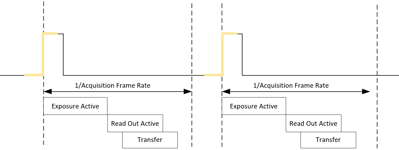
Hardware trigger is driven by external trigger source and starts exposing the image as soon as the camera receives a valid signal. Because the signal is driven by hardware, it has excellent timeliness and is suitable for scenarios with high synchronization and real-time performance. As shown in the diagram below:
Setting the 3D ToF camera to hardware trigger mode
1. Setting the camera to hardwaretrigger mode by ScepterGUITool
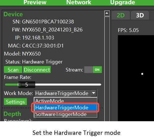
Connect and open the camera by ScepterGUITool, setting the camera’s Work Mode to hardware trigger mode, then turn on Stream. As shown in the diagram below:
2. Set the camera to hardware trigger mode by using the Scepter SDK
To implement the hardware trigger function using the Scepter SDK, refer to the DeviceHWTriggerMode example.
Sample code:
BaseSDK/Windows/Samples/Base/NYX650/DeviceHWTriggerMode.
After the example is compiled and run, the camera enters the hardware trigger mode and sets the open stream, waiting for the image to be obtained. After sending a valid hardware trigger signal through the EXT_Trigger pin of the camera, the image can be received. If the trigger signal is not sent in time, the program will report an error because the wait times out. Read the example source code for details.
Hardware trigger signal requirements and parameter settings
1) Driving capability of the trigger signal
The ToF camera from Vzense has the following requirements for hard trigger signals: The hardware trigger signal needs a voltage range of 3.3V~20V, and the driving current capacity should be above 5mA. It is recommended to add a decoupling circuit to the EXT_Trigger pin to avoid incorrect triggering caused by pulses.
2)Trigger signal polarity
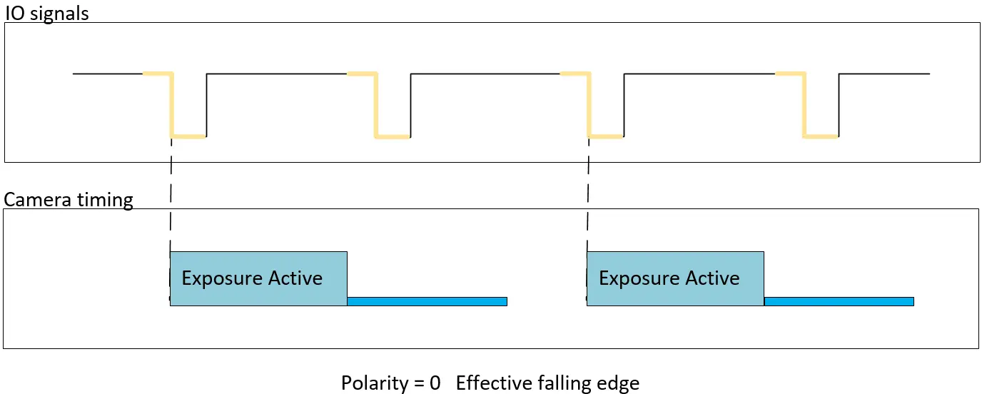
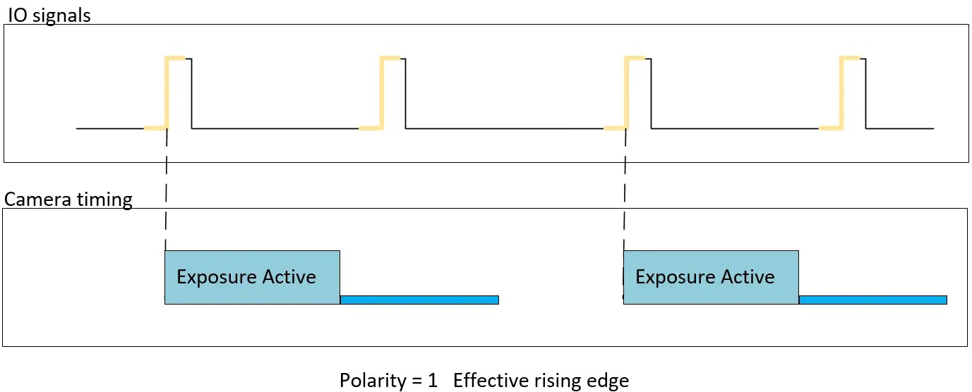
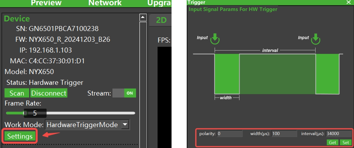
polarity: The polarity of the signal effectiveness detection. 0 indicates active low level and 1 indicates high level flat valid, value range is [0,1] , as shown in the diagram below:
3) Trigger signal width
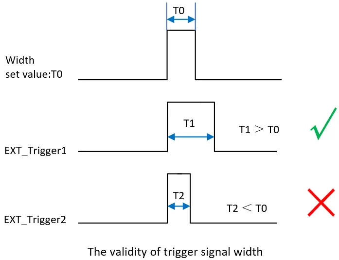
This parameter indicates the minimum effective signal width T0 that can be triggered successfully. If the signal width is smaller than this value, it cannot be triggered succesfully. It is recommended that the actual hardware trigger signal width be [T0+100us, T0+2000us]. This setting can be used to filter out the pulse interference in the trigger signal (which often appears as a narrower pulse), and the effective signal is often wider than the interference.
For example, T0 is the trigger signal pulse width setting as shown in the figure below:
If EXT_Trigger1, T1>T0, the trigger signal is valid and can be triggered.
If EXT_Trigger2 is T2<T0, the trigger signal is invalid and cannot be triggered.
4) Trigger signal interval
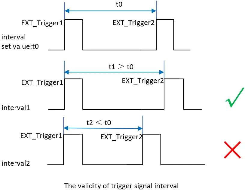
This parameter is the minimum interval between two consecutive trigger signals. If the interval is smaller than the preset interval value, the signal will not respond. The Interval value t0 determines the maximum frame rate of the camera in hard trigger mode, it can be used to filter out unwanted noise signal on the trigger signal. The unit of Interval is us. The value range is [34,000, 65535]. As shown in the following picture:
Interval1, t1>t0, trigger signal EXT_Trigger2 response;
Interval2, t2<t0, trigger signal EXT_Trigger2 no response.
5) Setting hardware trigger signal parameters by using ScepterGUITool
As shown below, click “Settings” to set the hard trigger parameters in the pop-up dialog box.
6) Use the Scepter SDK to configure hardware trigger signal parameters
The API interface is as follows:
//Set the input signal parameters for Hardware Trigger.parameters can be set with width, interval and polarity.
ScStatus scSetInputSignalParamsForHWTrigger(ScDeviceHandle device, ScInputSignalParamsForHWTrigger params);

//Get the signal parameters with width, interval and polarity.
ScStatus scGetInputSignalParamsForHWTrigger(ScDeviceHandle device, ScInputSignalParamsForHWTrigger* pParams);Hardware triggered input signal parameters struct type:
/**
 * @brief        Input signal parameters for Hardware Trigger.
 */
typedef struct
{
    uint16_t width;                  // Range in [1,65535]. The width of input signal.
    uint16_t interval;               // Range in [34000,65535]. The interval of input signal.
    uint8_t  polarity;               // Range in [0,1]. 0 for active low; 1 for active high.
} ScInputSignalParamsForHWTrigger; Hardware trigger pin connection
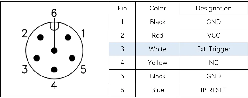
Vzense cameras use M8 type A multi-function interface, find the hardware trigger Ext_Trigger signal No. 3 white pin, and connect the signal cable of the external trigger source to this pin, connect the ground wire of the external trigger source to pin No. 1 or 5, you can use the hardware trigger function.
What is software trigger?
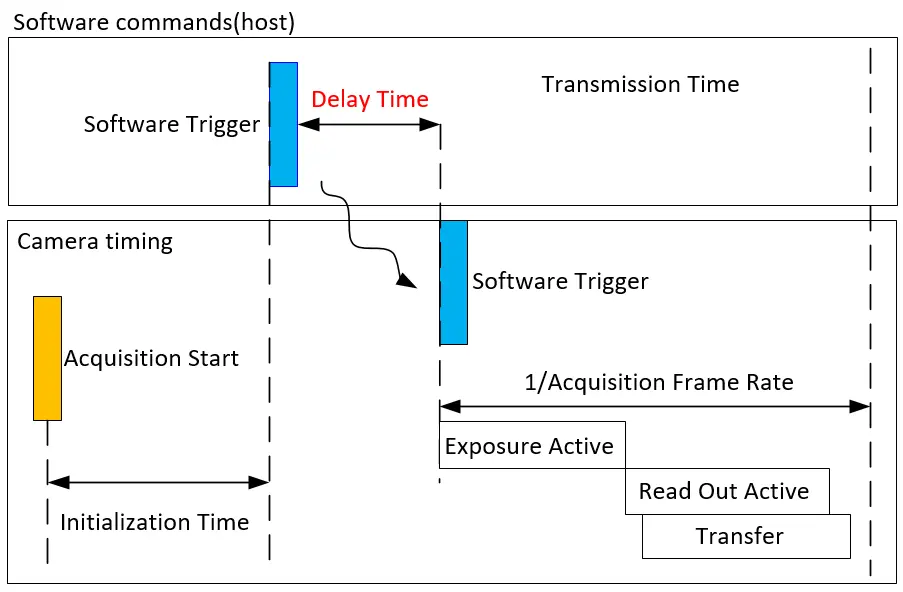
Unlike hardware trigger, software trigger mode doesn’t need external trigger source is required, and a frame trigger can happen by calling the software trigger command API. Using of software command communication, because the software command often has a delay of several ms, the real-time is not as good as hardware trigger, but it is easy to use and does not require a physical connection.
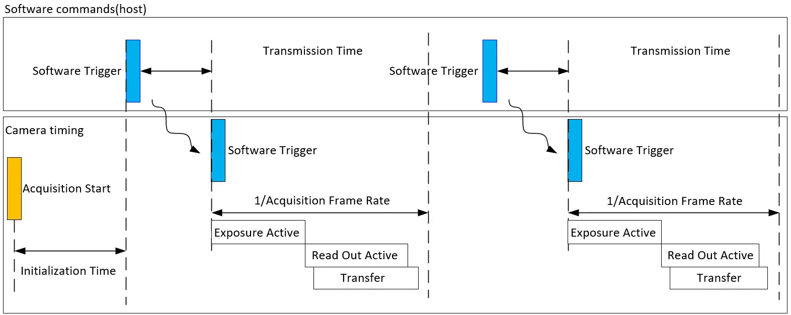
Setting the 3D ToF camera to software trigger mode
1. Setting the camera to software trigger mode by ScepterGUITool
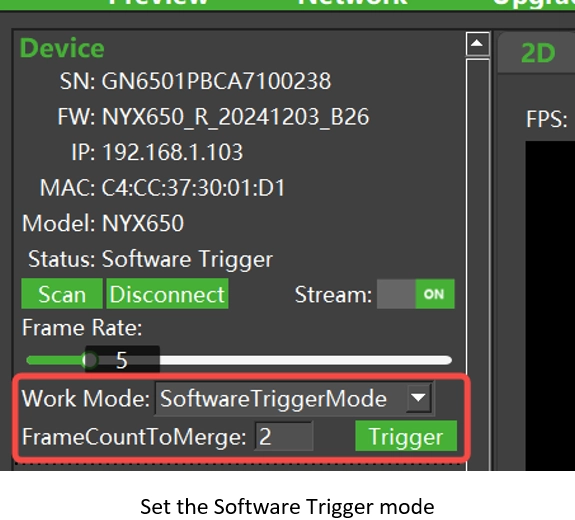
To enable the software trigger function by using ScepterGUITool, you need to set the camera’s Work Mode to “SoftwareTriggerMode”, set the “FrameCountToMerge” number and then select Stream set to “ON” . Then click “Trigger” to send a soft trigger command and receive an image. As shown in the following picture:
2. Setting the camera to software trigger mode by using the Scepter SDK
Setting the software trigger mode could refer to the DeviceSWTriggerMode example. Setting the software trigger parameter could refer to the DeviceSetSoftwareTriggerParameter example.
Sample code:
BaseSDK/Windows/Samples/Base/NYX650/DeviceSWTriggerMode.
BaseSDK/Windows/Samples/Base/NYX650/DeviceSetSoftwareTriggerParameter.
After the example is compiled and run, the camera enters the software trigger mode and sets the open stream, the program will send the software trigger command and wait for the image to be obtained. Read the example source code for details.
User can send a software trigger command by below software API:
//Set the count of frame in SC_SOFTWARE_TRIGGER_MODE
ScStatus scSetSoftwareTriggerParameter(ScDeviceHandle device, uint8_t frameCount);
//Get the count of framer in SC_SOFTWARE_TRIGGER_MODE
ScStatus scGetSoftwareTriggerParameter(ScDeviceHandle device, uint8_t* pframeCount);

//The camera is Triggering in once frame in SC_SOFTWARE_TRIGGER_MODE
ScStatus scSoftwareTriggerOnce(ScDeviceHandle device);Delay of software trigger command
Typical software trigger command transmission from the host to the device takes about 2 to 3ms, but it also depends on the host performance and network load.
