The time of flight system measures the distance by the time difference between the emission and reception of the modulated infrared light. Assuming the emission of modulated frequency f light, the speed of light is C in one cycle, we can measure the maximum range dmax=c/2f. We can adjust the frequency to obtain the desired measuring distance. As the frequency increases, the accuracy and precision will be higher, but the increase in frequency will bring about a reduction in the measurement range. This will occur when the first cycle of modulated light is emitted to a distant target object, and the first cycle of modulated light is returned when the object is detected, during which the second cycle of modulated light has been emitted, making it impossible for the sensor to distinguish which cycle of modulated light is being received. This phenomenon is what we call “range aliasing”, alternatively, other scholars will refer to it as “range folding” or “unambiguous range” or “second-trip echo” or “phase wrap”. Let us learn more about it.
Table of Contents
An example of range aliasing
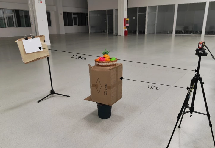
The current camera frequency is 120MHZ, and the maximum distance measured is 1.249m. Now place object A 1.05m away from the camera for true detection, place object B 2.299m away from the camera for true detection, as shown in the figure below:
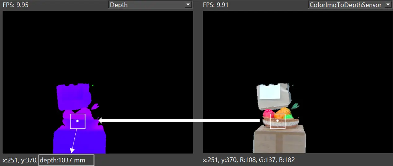
The Depth and RGB image in the camera are shown below, the depth of the measured object A is 1.037 m. Obviously not out of cycle, the measured depth value equals the true value.
The depth and RGB image in the camera are shown below, the depth of the measured object B is 1.035m. Obviously, the maximum measurement range of this frequency is exceeded, and the phenomenon of range aliasing occurs, the measured value is not equal to the true value.
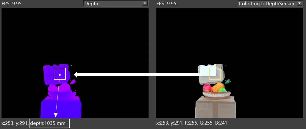
As can be seen from the above picture, the depth map measurements of object A and object B are the same, but the true positions are not the same. Range aliasing occurs for object B, but not for object A.
What are the causes of range aliasing?
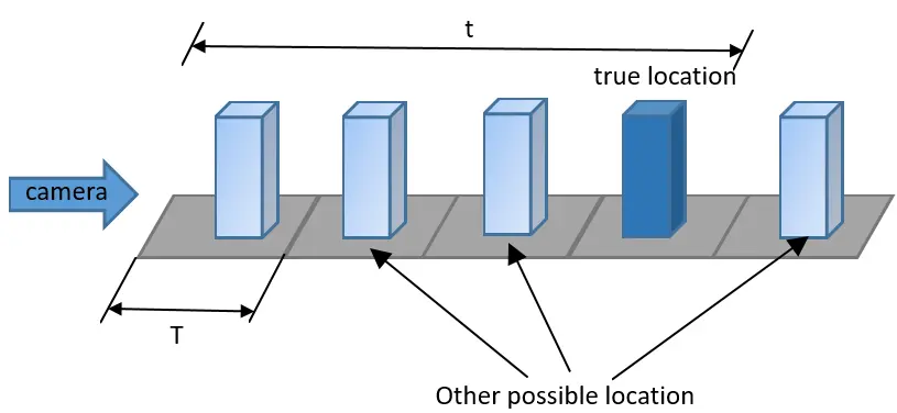
Based on the above phenomena, it can be concluded that when the time t for light to travel back and forth is greater than the period of the modulated light, the distance measurement is incorrect. Assuming that the modulated infrared light emitted by the sensor hits the target object with a round trip time t, there are three cases as follows:
If t < T, then the return signal arrives before the next cycle of modulated light emission;
If t = T, then the return signal arrives exactly when the next cycle of modulated light is emitted;
If t > T, then the return signal arrives after the next cycle of modulated light emission.
In the third case the ranges aliasing and there is ambiguity in the measurements, the sensor is unable to determine whether the return signal is from the first or some other cycle and is unable to get the corresponding phase shift to calculate the true distance. Consequently, erroneous data values are obtained.
How to solve this phenomenon?
From the distance formula dmax=c/2f, it can be seen that low-frequency modulation can measure a longer detection distance, but it will affect the accuracy and precision of the measurement; high-frequency modulation can obtain higher accuracy and precision, but the measured distance is limited. The relationship between them is shown in the figure below:
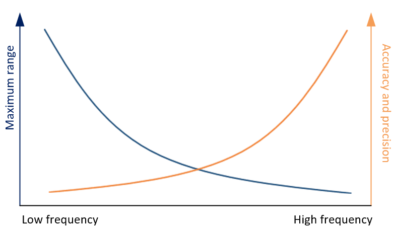
So we can use multi-frequency techniques to improve this problem. Multi-frequency technology allows you to increase the measurement distance without decreasing the modulation frequency. It works by adding one or more modulation frequencies to the current frequency, and since each frequency has a different blurring distance, the true measurement position is where the different frequencies coincident. At present, our ToF system uses “TN04-What is the dual-frequency modulation of Continuous Wave indirect Time of Flight(CW-iToF)?“.
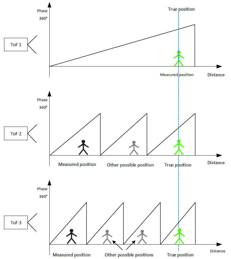
Of course, this technique cannot be perfect and has some limitations, requiring a sacrifice of frame rate, a large effect of motion artefacts, and a consequent increase in the depth computation error rate as the SNR decreases, requiring a choice of frame rate based on the actual situation.


