In science and technology terms, iToF is abbreviation of indirect Time-of-Flight. The working principle of iToF is that the camera itself emit modulated infrared light signals to target objects, the sensor receives the light signals returned from the target object, and the distance measurement is realized by measuring the phase shift to calculate the time of flight of the measurement light. The current iToF has two major technical methods, based on the Continuous Wave method and the Pulse method. Let us learn the technical principles of both next.
Table of Contents
What is principles of continuous wave based technology?
The basic principle of Continuous Wave-indirect Time of Flight (CW-iToF) is to measure the phase shift between the emitting and receiving of a cycle by modulating the light into a square wave of a certain frequency f, thus measuring the distance by calculating the phase shift. Assuming that the speed of light is C and the phase shift of one cycle is φ(0 ≤ φ ≤ 2π), the equation for the distance from the emitting end to the object can be obtained as:

How to calculate phase shift (φ)?
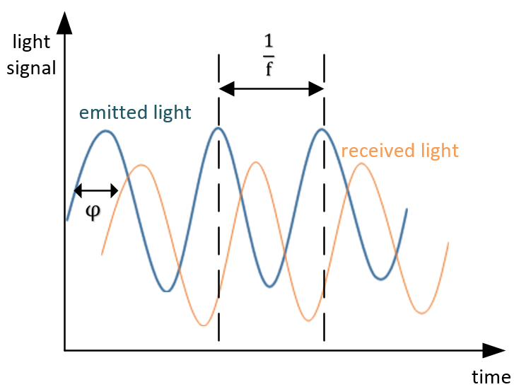
Take the single-frequency sinusoidal function as an example, the relationship between the transmitted wave and the received wave is shown below:
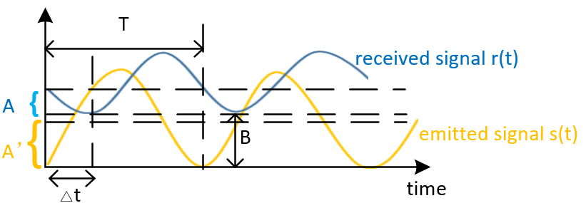
Assume that the equation for the emitted waveform is:

The received waveform equation is:

φ means the phase shift from the emitting time to the receiving time, the traveling time of light can be calculated from the φ easily. Since it is difficult to measure the speed of light directly, the camera modulates the laser emitter into four phase energy maps with different time shifts, of 0°,90°, 180°, 270°, The energy captured by the four different phase receiving windows is shown below:
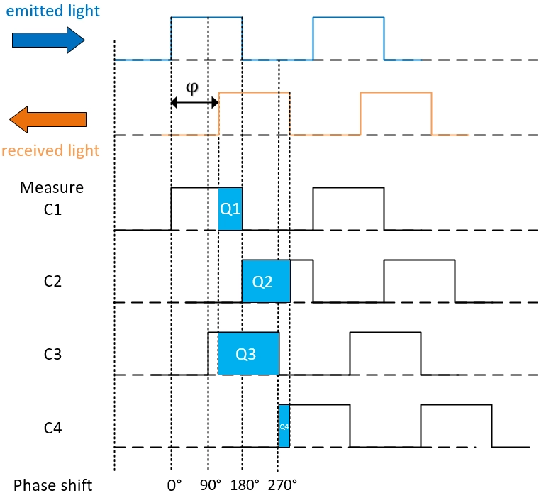
The integral energy values are:

Bringing φ into the equation d gives the distance, from this (0 ≤ φ ≤ 2π), it can be seen that the range of measurements that can be obtained is [0 ~ dmax=2π], when φ=2π takes the theoretical maximum value, and the maximum value is:

Problems with CW- iToF
Since the light is modulated into a specific frequency, the maximum range can be determined based on the modulation frequency in use. When the light travels back and forth for a period greater than the period of the modulated light, then the distance calculation will be wrong because it is impossible to distinguish between signals coming back from far away and signals coming back from near with the same phase shift, but in different cycles. This will produce a phenomenon known as “Range Aliasing”. Take 120MHZ for example,common frequencies and theoretical Maximums:


Common frequencies and theoretical Maximums:
| Frequency | 100MHZ | 80MHZ | 60MHZ | 20MHZ | 15MHZ | 10MHZ |
| Maximum detection range | 1.5m | 1.875m | 2.5m | 7.5m | 10m | 15m |
What is principle of pulse based technology?
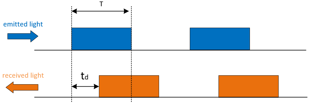
The basic principle of Pulse-indirect Time of Flight (P-iToF) is to emit a repetitive pulse signal and analyze the phase of the pulse signal to obtain depth. Assuming that the speed of light is C, and the flight time is td, then the distance formula is:

How to calculate flight time (td)?
P-iToF improves the accuracy by double sampling technique. The camera needs to modulate the laser emission end into 2 phase energy maps with different time shift, of 0°, 180°, additionally, turns on when no light pulses are emitted, collecting only the background light signal. As shown in the figure below:
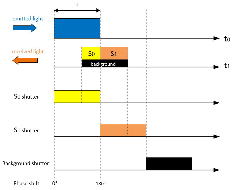
Based on the corresponding ratios it is possible to calculate td:

Bringing td into the equation d gives the distance:

The distance calculation formula that includes the background light signal is as follows:

Comparison of two technology
| CW-iToF | P-iToF | |
| Power consumption | Low | |
| Light resistant | Strong | |
| Frame rate | High | |
| Accuracy and precision | High | |
| Jitter | Little |


