Due to the 3D camera principles of ToF technology, different parameter configurations can result in varying performance for ToF cameras. Therefore, for different application scenarios, the parameters of the Vzense ToF camera need to be configured accordingly. This article summarizes the parameter definitions of the Vzense 3D ToF camera and provides configuration recommendations.
Table of Contents
Parameter summary
| Pros | Cons | |
| Frame rate | Higher frame rate means faster speed | The maximum exposure time is smaller |
| Exposure time | Higher exposure time reduces jitter and improves the effect on black objects | Easily light saturate, prone to ghosting |
| Spatial filtering | Smoothes the point cloud, reduces jitter | Loss of detail in transition areas |
| Time filtering | Smoothes the point cloud, reduces jitter | Greatly increases ghosting, not suitable for moving scenarios |
| Confidence filtering | Filter out low signal-to-noise ratio areas | Not suitable for low reflectivity scenes |
| Working modes (Active, Hardware Trigger, Software Trigger) | Active Mode: Continuous imaging, suitable for continuous monitoring scenarios Hardware Trigger: High real-time performance, accurate time synchronization Software Trigger: No additional wiring required | Active Mode: Low real-time performance, high power consumption Hardware Trigger: Requires additional wiring to the trigger source Software Trigger: Real-time performance of software command sending is low |
| IR Gain | Adjust IR image brightness as needed by the scene | — |
| Gamma Correction | Adjust Gamma correction according to the scene to modify image contrast | — |
| RGB resolution | High resolution, clear images | Increased data volume, causing delays in network transmission, storage, decoding, and increased host loading |
| RGB exposure mode | Active exposure:No need to adjust, automatically adapts to the environment, adjusts exposure Manual exposure: Fixed exposure time, not affected by environmental changes | Active exposure: Requires several frame transitions, not suitable for trigger mode Manual exposure: Requires manual setting, suitable for stable lighting environments |
| RGB auto exposure time | Generally does not need to be modified, automatically set according to frame rate, can be limited according to scene requirements | — |
| RGB manual exposure time | Adjust image brightness according to scene requirements, generally used in stable lighting environments | — |
| HDR | Capture high and low reflectivity objects in the scene simultaneously | Requires multi-frame fusion, overall frame rate reduction, not suitable for motion scenarios |
| WDR (NYX exclusive) | Increase the measurement range from nearest to farthest | Requires multi-frame fusion, which lowers the overall frame rate and is not conducive to motion scenarios. Transition areas between near and far distances may have errors. |
| Pulse width (NYX Series) | The larger the pulse width, the greater the detection range, but the absolute and relative accuracy will decrease. Conversely, the smaller the pulse width, the smaller the detection range, improving absolute and relative accuracy | — |
Configuration recommendations
1. Check the camera installation environment for obstructions, covers, anything affecting heat dissipation, near-range objects, and high reflectivity objects.
2. For non-continuous monitoring scenarios, use triggering to reduce power consumption.
3. Lower the frame rate to reduce power consumption and achieve maximum exposure time, improving the depth map effect.
4. As long as it does not cause light saturate or stray light, longer exposure times are better for improving the depth map effect.
5. The lower the RGB resolution, the better, as long as it meets user needs. This can improve transmission delays, processor loading, etc.
6. In motionless scenes, turn on time filtering to improve depth map quality; in moving scenes, turn off time filtering to avoid motion trailing.
7. Avoid using HDR and WDR functions, especially in moving scenes, to prevent motion ghosting.
8. Increase exposure time or lower the confidence filter when capturing low reflectivity objects.
9. If the maximum distance does not exceed 3 meters, use the narrower pulse width NYX650S for higher precision.
10. For areas with invalid data, analyze the reasons using the IR image.
Invalid point analysis
In many scenarios, ToF cameras cannot measure the distance value of every pixel in the image. These distance values are often marked as invalid points (with a value of 0). As shown in the image below, the black areas represent points that the ToF camera cannot measure.
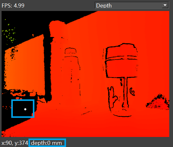
Reasons for invalid data output from ToF cameras:
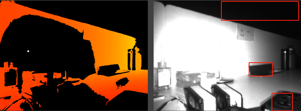
1. Confidence filtering
Due to long distances or low reflectivity of the target object, the reflected signal from the ToF camera is too weak and gets filtered out by the confidence filter. This can be determined by observing the IR image or decreasing the confidence filter threshold. In the red boxed area of the image below, the IR image values are very low, indicating a weak reflected signal.
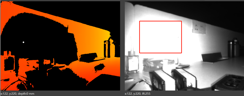
2. Near-range light over saturate
Caused by near-range light over saturate, which can be determined by observing the IR image. As shown in the image below, the red boxed area indicates an overly strong signal, with the IR image displaying high brightness and over saturate(IR value of 255), resulting in missing depth data.
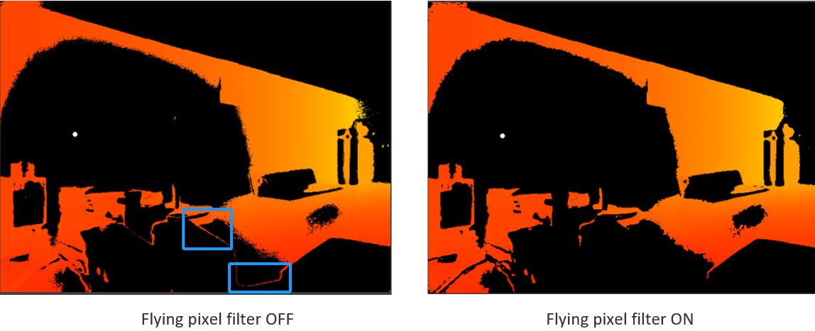
3. Flying pixel filtering
Filtered out by flying pixel filtering, which usually occurs at the edges of objects. This can be determined by switching the flying pixel filter on and off. As shown in the images below, the edges of the objects in the blue box in the left image disappear in the right image when the flying pixel filter is turned on.
4. Stray light
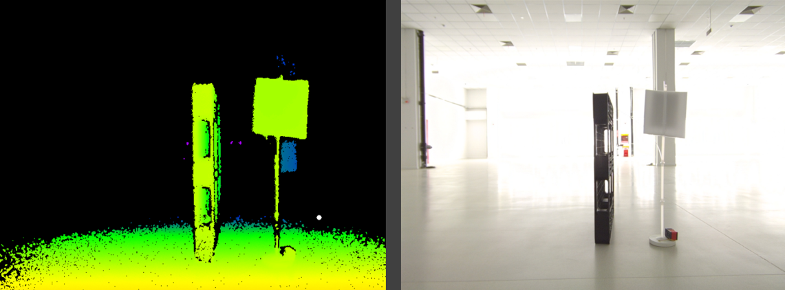
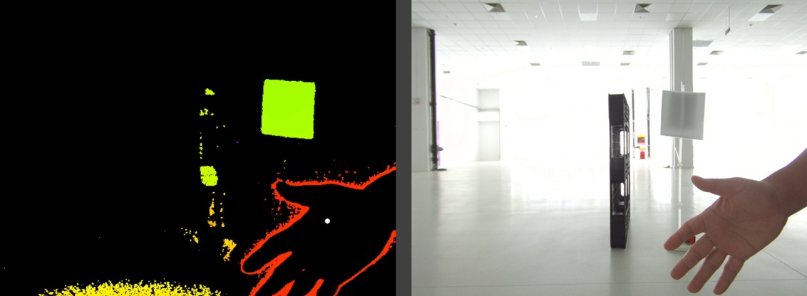
For CW-iToF(Continuous Wave-indirect Time-of-Flight), due to the dual-frequency period calculation being filtered out, it usually occurs when stray light is present, causing errors in depth data calculation and indirectly leading to dual-frequency calculation failure, resulting in invalid data. This issue is subtle and cannot be pinpointed using the Depth image. You can check the IR image to see if there are bright objects or near objects that might cause stray light, or check if the camera is obstructed by covers.
As shown in the image below, the target objects are a low reflectivity black pallet and a high reflectivity white cardboard. Under normal conditions, both objects can be recognized.
As shown in the image below, when a near object (hand) appears, many depth data points of the black pallet become invalid. No parameter configuration was changed during this process. This is due to the stray light caused by the near object (hand), which results in a significant deviation in the black pallet’s data, making it impossible to complete the dual-frequency period calculation. On the other hand, the white cardboard, due to its higher reflectivity, is less affected by stray light and does not show invalid data.
5. Unwrapping period
For Continuous Wave indirect Time of Flight (CW-iToF), due to errors in dual-frequency period decoding, invalid data are produced and filtered out by the algorithm. This typically occurs in situations prone to stray light and multi-path interference, causing errors in depth data calculation and indirectly leading to dual-frequency decoding failure, resulting in invalid points.


