Table of Contents
Introduction to PTP
PTP (Precision Time Protocol) originates from the IEEE 1588 standard, which was first published in 2002. PTP is designed to provide high-precision time synchronization and is suitable for both WAN and LAN environments. The development of PTP stems from the need for traditional time synchronization protocols such as NTP to meet the needs of some application areas. In areas such as industrial automation, communications, and financial transactions, more precise time synchronization is required to ensure system coordination and accuracy.
PTP utilizes clock devices in the network for time synchronization, which is achieved by passing precise timestamps across the network. It uses a master-slave architecture, with one node acting as the master clock and the other nodes acting as slave clocks. The master clock synchronizes with the slave clock by sending timestamp packets, and the slave clock adjusts its own clock by receiving and processing these messages. With the continuous development of technology, PTP has also undergone several updates and improvements, and the most popular version at the moment is PTPv2. PTPv2 adds some new features and improvements to further improve the accuracy and reliability of time synchronization.
Principle of synchronous computing
Based on the certainty of PTP architecture design (both ends of the same link, the transmission delay is the same), the synchronization between the master and the slave is realized, and the process is as follows:
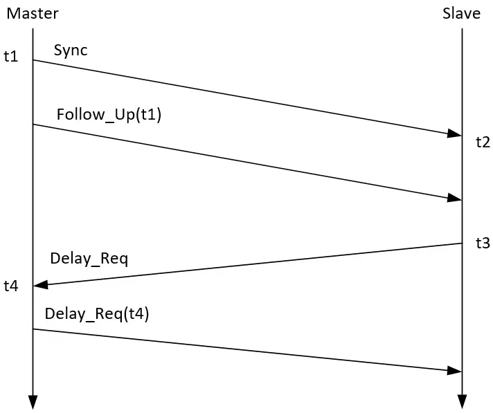
1) The master sends a Sync packet to the slave at t1 and saves the t1 time locally, and the slave records the local time t2 after receiving the packet;
2) The master then sends Follow_Up packet to send the t1 moment to the slave;
3) After receiving the Follow_Up packet, the slave sends Delay_Req packet to the master and records the sending time t3;
4) The master receives the Delay_Req packet, records the receiving moment t4, and returns the t4 value to the slave through the Delay_Resp packet.
From the t1, t2, t3, and t4 values obtained above, the offset value can be calculated by the slave. The formula is derived as follows:
Suppose the time difference is T_offset
T_master = Tslave + T_offset
Assume that the transmission delay is t_transport
t1 + t_transport = t2 + T_offset
t3 + t_transport = t4 - T_offset
t1 - t3 = t2 - t4 + 2*T_offset
T_offset = (t1 + t4 - t3 - t2)/2
Classification of synchronous clocks
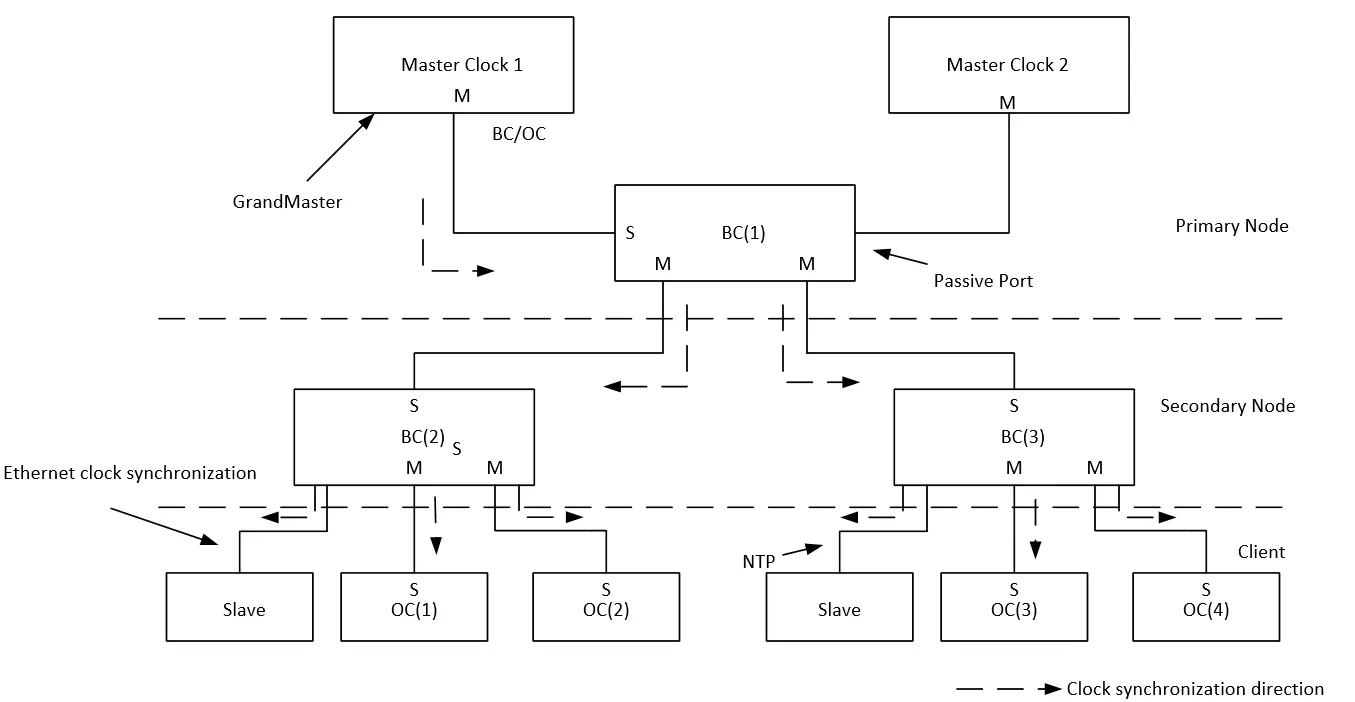
PTP consists of two different types of clock processing: hard clock and soft clock. As shown in the figure below:
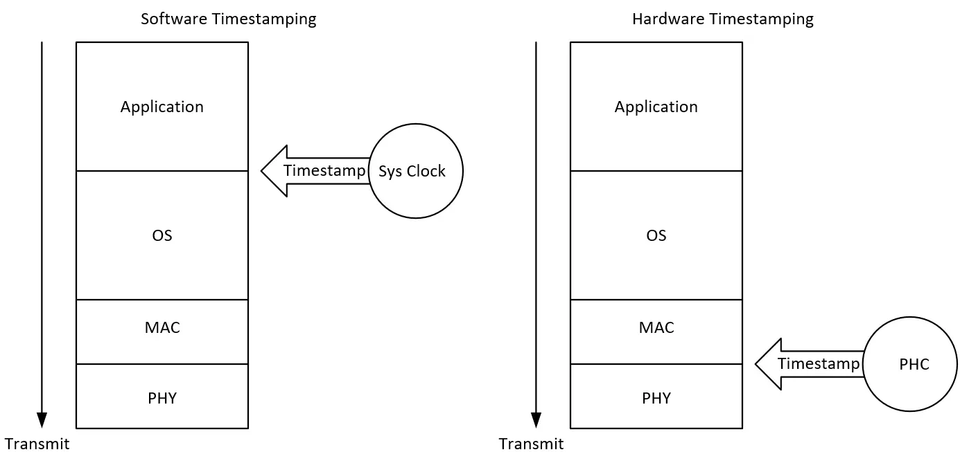
Soft clocks use standard Ethernet modules to implement the PTP protocol in software, and since the timestamp information is at the application layer, the delay fluctuations introduced by the software stack running on the master and slave devices mean that only limited accuracy can be achieved.
The hard clock is closer to the physical interface, which minimizes the impact of stack latency, so the synchronization accuracy is higher.
PTP hard clock
MAC addresses are used to encapsulate packets and transmit them on Layer 2 links, requiring hardware to support the sending and receiving of PTP packets. For example, the role of the switch is the second-level node in the following figure, and it needs to be both a master and a slave in the network. Therefore, the PTP hard clock network needs to be supported by all network node devices, otherwise it cannot be networked. Because of the hardware support of the whole network, the synchronization accuracy is very high, and the actual measurement of the LAN can reach about 700ns. As shown in the figure below:
PTP soft clock
The soft clock is implemented by an application, and packets can be encapsulated using UDP or MAC. UDP encapsulation is sent down through UDP/IP stack packets, and MAC packets skip the IP protocol stack and are sent directly through MAC addresses, so MAC packets have higher accuracy than the two types of software packets.
MAC encapsulation, as shown in the figure below:

UDP encapsulation, as shown in the figure below:

The advantage of soft clocks is that they can be used without special hardware support, and although the synchronization accuracy is lower than that of hard clocks, it can also meet most use cases. Laboratory test data, up to about 3us in LAN.
Vzense 3D ToF camera PTP mode
Due to the high cost of hard clock networking, which requires the support of all devices on the LAN, soft clock mode is used for synchronization except for high-precision scenarios.
In Vzense cameras, the IEEE 1588v2 standard is used, and only PTP soft clock mode is supported for the time being.
Delay Mechanism: E2E

Network Transport: UDP IPv4

Time Stamping: Software

Role: SlaveOnly
Configuration method
PTP is used in master-slave mode, and the active camera is used as the PTP slave, so the PTP master needs to exist and be configured on the LAN.
PTP Master configuration
There are many different forms of PTP Master, such as industrial computer and dedicated PTP master clock server. In this article, we will use Linux (Ubuntu) as an example to build a PTP master clock.
Notes: The PTP Master function is not supported on Windows desktops.
Use the command to install the ptp tool ptp4l.
$ sudo apt update
$ sudo apt install linuxptp -y
After the installation is complete, run the following command to ensure that the installation is successful:
$ ptp4l -v
1.8

$ ptp4l -h

usage: ptp4l [options]

 Delay Mechanism

 -A        Auto, starting with E2E
 -E        E2E, delay request-response (default)
 -P        P2P, peer delay mechanism

 Network Transport

 -2        IEEE 802.3
 -4        UDP IPV4 (default)
 -6        UDP IPV6

 Time Stamping

 -H        HARDWARE (default)
 -S        SOFTWARE
 -L        LEGACY HW

 Other Options

 -f [file] read configuration from 'file'
 -i [dev]  interface device to use, for example 'eth0'
           (may be specified multiple times)
 -p [dev]  PTP hardware clock device to use, default auto
           (ignored for SOFTWARE/LEGACY HW time stamping)
 -s        slave only mode (overrides configuration file)
 -l [num]  set the logging level to 'num'
 -m        print messages to stdout
 -q        do not print messages to the syslog
 -v        prints the software version and exits
 -h        prints this message and exits
After the installation is complete, run the following command to start:
$ sudo ptp4l -S -i eth0 -m

ptp4l[629168.570]: port 1: INITIALIZING to LISTENING on INITIALIZE
ptp4l[629168.574]: port 0: INITIALIZING to LISTENING on INITIALIZE
ptp4l[629168.576]: port 1: link up
ptp4l[629175.157]: port 1: LISTENING to MASTER on ANNOUNCE_RECEIPT_TIMEOUT_EXPIRES
ptp4l[629175.158]: selected best master clock 4e275b.fffe.06c9d6
ptp4l[629175.158]: assuming the grand master role
-S: Software Clock
-i:Required network interface card (mandatory), view the network interface card name through ifconfig
-m: Running in the foreground (optional), the foreground is convenient to view the running log
eth0: Network interface
The above completes the configuration of the PTP Master.
Notes: The parameters of PTP4L are slightly different in different versions, please use the output reference of -h for details.
PTP Slave configuration (Vzense camera)
Use a camera that supports PTP Slave, such as the NYX650 (please refer to the datasheet for whether the specific model supports PTP).
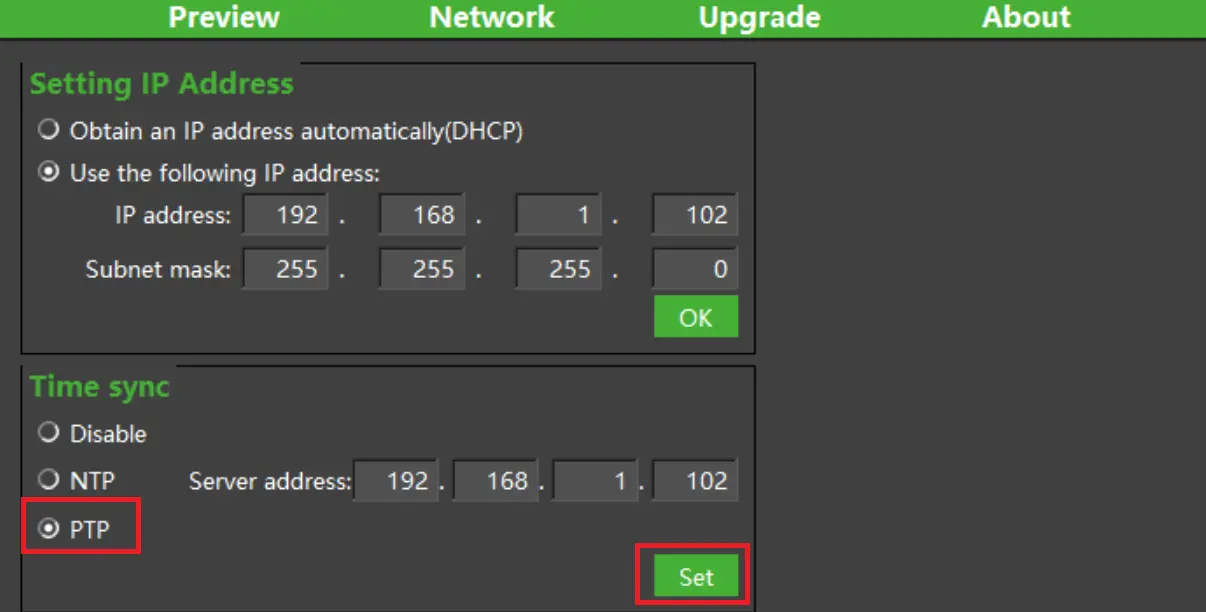
Method 1: Setting with ScepterGUITool
Open “ScepterGUITool.exe“, search for and connect the camera. After the connection is successful, open the “Network” page. As shown in the figure below:
Method 2: Setting with software API
Sample code:
BaseSDK/Windows/Samples/Base/NYX650/DeviceSetPTP.
Struct Type:
typedef struct
{
    uint8_t flag;     //!< 0: disable, 1: NTP, 2: PTP, only NTP needs the ip.
    uint8_t ip[16];   //!< just for NTP.
} ScTimeSyncConfig;
PTP enable can be set or obtained by below API:
//Set the parameters for enable the PTP time sync
ScStatus scSetRealTimeSyncConfig(ScDeviceHandle device, ScTimeSyncConfig params);
//Get the parameters for the status of PTP time sync
ScStatus scGetRealTimeSyncConfig(ScDeviceHandle device, ScTimeSyncConfig* pParams);
Notes:
1) The camera supports PTP’s real-time setting enabled, which can take effect immediately. After the setting is successful, the camera will also record and enable this function, and it will still be used by default the next time the camera is powered on.
2) If the setup fails, please confirm whether the camera model you are using supports the PTP function, and if so, contact FAE to confirm whether the current firmware version supports it.
Verification method
After the camera is set successfully, the PTP synchronization and timing function is enabled by default. How do I know if the camera has been successfully synchronized with the PTP server? Verification can be checked by printing the timestamp of the acquired image.
typedef struct
{
    uint32_t      frameIndex;        //The index of the frame.
    ScFrameType   frameType;         //The type of frame. See ::ScFrameType for more information.
    ScPixelFormat pixelFormat;       /*The pixel format used by a frame. See ::ScPixelFormat for more
                                       information.*/
    uint8_t*      pFrameData;        //A buffer containing the frame’s image data.
    uint32_t      dataLen;           //The length of pFrame, in bytes.
    uint16_t      width;             //The width of the frame, in pixels.
    uint16_t      height;            //The height of the frame, in pixels.
    uint64_t      deviceTimestamp;   /*The timestamp(in milliseconds) when the frame be generated on the
                                       device. Frame processing and transfer time are not included.*/
} ScFrame;
Include a deviceTimestamp member in the struct of the image acquisition with a UNIX timestamp of uint64. The code(Sample code: BaseSDK/Windows/Samples/Base/NYX650/FrameCaptureAndSave)for adding the print timestamp to the drawing routine of samples is as follows:
//1.ReadNextFrame.
//2.GetFrame acoording to Ready flag and Frametype.
for(int i = 0;i < frameSpace;i++)
{
    status = scGetFrameReady(deviceHandle, 1200, &FrameReady);
    if (status != ScStatus::SC_OK)
    {
        cout << "scGetFrameReady failed status:" <<status<< endl;
        continue;
    }
    //depthFrame for example.
    if(1 == FrameReady.depth)
    {
        status = scGetFrame(deviceHandle, SC_DEPTH_FRAME, &depthFrame);
        if (depthFrame.pFrameData != NULL)
        {
            cout << "get Frame successful,status:" << status << "  ";
            cout << "deviceTimestamp:" << depthFrame.deviceTimestamp <<  endl;
        }
    }
}
When the code is executed, the deviceTimestamp value will be printed when the graph is successfully retrieved. If PTP synchronization is not set, or if the camera is powered off and powered on again, the following logs are printed:
---FrameCaptureAndSave---
Get device count: 1
serialNumber:GN6501CBCA3310168
ip:192.168.1.102
connectStatus:1
get Frame successful,status:0  deviceTimestamp:18224
get Frame successful,status:0  deviceTimestamp:18257
get Frame successful,status:0  deviceTimestamp:18291
get Frame successful,status:0  deviceTimestamp:18324
get Frame successful,status:0  deviceTimestamp:18357
get Frame successful,status:0  deviceTimestamp:18391
get Frame successful,status:0  deviceTimestamp:18424
get Frame successful,status:0  deviceTimestamp:18457
get Frame successful,status:0  deviceTimestamp:18491
get Frame successful,status:0  deviceTimestamp:18524
get Frame successful,status:0  deviceTimestamp:18557
get Frame successful,status:0  deviceTimestamp:18591
get Frame successful,status:0  deviceTimestamp:18624
get Frame successful,status:0  deviceTimestamp:18657
get Frame successful,status:0  deviceTimestamp:18691
get Frame successful,status:0  deviceTimestamp:18724
get Frame successful,status:0  deviceTimestamp:18757
get Frame successful,status:0  deviceTimestamp:18791
get Frame successful,status:0  deviceTimestamp:18824
get Frame successful,status:0  deviceTimestamp:18857
---end---
After the PTP synchronization is configured, the following logs are printed:
---FrameCaptureAndSave---
Get device count: 1
serialNumber:GN6501CBCA3310168
ip:192.168.1.102
connectStatus:1
get Frame successful,status:0  deviceTimestamp:1719910682528
get Frame successful,status:0  deviceTimestamp:1719910682562
get Frame successful,status:0  deviceTimestamp:1719910682595
get Frame successful,status:0  deviceTimestamp:1719910682629
get Frame successful,status:0  deviceTimestamp:1719910682662
get Frame successful,status:0  deviceTimestamp:1719910682695
get Frame successful,status:0  deviceTimestamp:1719910682728
get Frame successful,status:0  deviceTimestamp:1719910682762
get Frame successful,status:0  deviceTimestamp:1719910682795
get Frame successful,status:0  deviceTimestamp:1719910682828
get Frame successful,status:0  deviceTimestamp:1719910682862
get Frame successful,status:0  deviceTimestamp:1719910682895
get Frame successful,status:0  deviceTimestamp:1719910682928
get Frame successful,status:0  deviceTimestamp:1719910682962
get Frame successful,status:0  deviceTimestamp:1719910682995
get Frame successful,status:0  deviceTimestamp:1719910683029
get Frame successful,status:0  deviceTimestamp:1719910683062
get Frame successful,status:0  deviceTimestamp:1719910683096
get Frame successful,status:0  deviceTimestamp:1719910683129
get Frame successful,status:0  deviceTimestamp:1719910683162
---end---
There will be a significant difference in the timestamp print value, because the default start timestamp used by the camera is 0, and after the PTP time is synchronized, it will be changed to the system time of the master.
Further confirmation can also be done through RTC time conversion, the reference code is as follows:
#include <time.h> //Reference c library functions

/*
Omit part of code
*/

if (depthFrame.pFrameData != NULL)
{
    struct tm *p;
    time_t t;
    char s[100];
    cout << "get Frame successful,status:" << status << "  ";
    t = depthFrame.deviceTimestamp/1000;
    p = gmtime(&t);
    strftime(s, sizeof(s), "%Y-%m-%d %H:%M:%S", p);
    printf("%d: %s\n", (int)t, s);
}
After the run is successful, print the log:
---FrameCaptureAndSave---
Get device count: 1
serialNumber:GN6501CBCA3310168
ip:192.168.1.102
connectStatus:1
get Frame successful,status:0  1719911020: 2024-07-02 09:03:40
get Frame successful,status:0  1719911020: 2024-07-02 09:03:40
get Frame successful,status:0  1719911021: 2024-07-02 09:03:41
get Frame successful,status:0  1719911021: 2024-07-02 09:03:41
get Frame successful,status:0  1719911021: 2024-07-02 09:03:41
get Frame successful,status:0  1719911021: 2024-07-02 09:03:41
get Frame successful,status:0  1719911021: 2024-07-02 09:03:41
get Frame successful,status:0  1719911021: 2024-07-02 09:03:41
get Frame successful,status:0  1719911021: 2024-07-02 09:03:41
get Frame successful,status:0  1719911021: 2024-07-02 09:03:41
get Frame successful,status:0  1719911021: 2024-07-02 09:03:41
get Frame successful,status:0  1719911021: 2024-07-02 09:03:41
get Frame successful,status:0  1719911021: 2024-07-02 09:03:41
get Frame successful,status:0  1719911021: 2024-07-02 09:03:41
get Frame successful,status:0  1719911021: 2024-07-02 09:03:41
get Frame successful,status:0  1719911021: 2024-07-02 09:03:41
get Frame successful,status:0  1719911021: 2024-07-02 09:03:41
get Frame successful,status:0  1719911021: 2024-07-02 09:03:41
get Frame successful,status:0  1719911021: 2024-07-02 09:03:41
get Frame successful,status:0  1719911021: 2024-07-02 09:03:41
---end---
Notes:
1) The timestamp in the device is the moment when the image is generated, and does not include the delay of image processing and network transmission.
2) The timestamp used by the device is UTC time.
There is no RTC module in the camera, so it needs to be resynchronized with the master clock after each power-up. There is a time difference between the power on and the time synchronization of the camera, which will vary according to the network conditions (about 11s in normal environments), so if the host computer reads the image earlier, the timestamp of the image in the first few seconds will not be synchronized successfully.


