Table of Contents
One frame procedure of 3D ToF camera
The process from ToF(Time of Flight) exposure to user reading out a frame on the host can be summarized as follows:
- Exposure
- ISP processing
- Transmission
- SDK processing
- Program readout
Exposure and ISP processing is implemented in the camera side, SDK processing and program readout is implemented in the host side. The specific process is shown in the figure below:

Exposure Time
The exposure time of the camera consists of two parts: exposure and data transmission.
The exposure time composition for DS series products
1. When HDR is not enabled, the exposure time composition is as shown in the diagram below:

Users can adjust the exposure time as needed within the “ScepterGUITool”, as shown below:
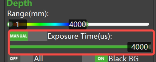
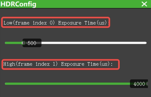
2. When HDR is enabled (refer to the product introduction to see if it is supported), the exposure time composition is as shown in the diagram below:

Users can adjust the exposure time as needed within the “ScepterGUITool”, as shown below:
The exposure time composition for NYX series products
1. When HDR is not enabled, the exposure time composition is as shown in the diagram below:

Users can adjust the exposure time as needed within the “ScepterGUITool”, as shown below:
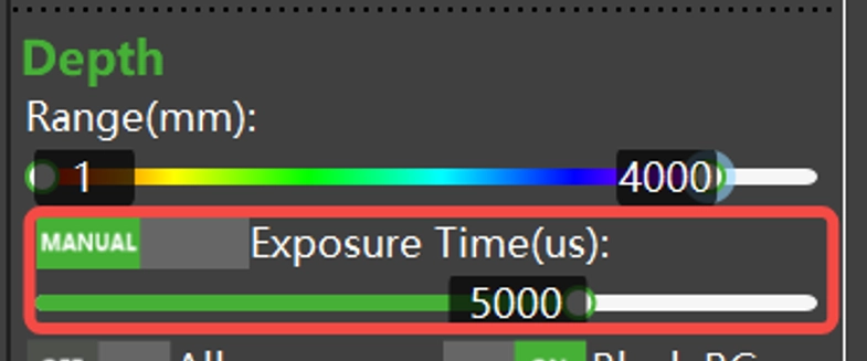
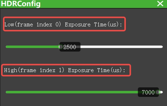
2. When HDR is enabled (refer to the product introduction to see if it is supported), the exposure time composition is as shown in the diagram below:

Users can adjust the exposure time as needed within the “ScepterGUITool”, as shown below:
Timestamp and frame index
What is timestamp?
When the Vzense 3D Time of Flight(ToF) camera is powered on, the camera system starts a local timer starting from 0. The timer automatically increases regardless of the working state of the camera.
Note: By default, the system time of the camera is not the real time clock which calibrated with the host time. If the user requires to calibrate the local time with the host time, the NTP/PTP method must be configured between the camera and the host. Please refer to application notes “AN05-NTP function settings for Vzense 3D Time of Flight (ToF) camera” and “AN06-PTP function settings for Vzense 3D Time of Flight (ToF) camera“.
At the end of each frame exposure, the camera will allocate each frame a timestamp (t), in 1ms unit. This timestamp will be sent to the host side along with the data for the frame image and is available through the API.
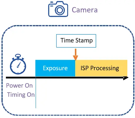
Timestamps can be used as alignment and calibration between the camera and the host system, especially in trigger mode, so that the occurrence time of a certain frame can be known at the application side to avoid uncertain delays in the calculation and transmission process, so as to align with the system time.
Frame index
When an image is transferred to the host, the host SDK assigns a unique frame index to each frame, starting at 0 and increasing in sequence. Frame index is assigned by the host SDK so it doesn’t matter with the exposure, ISP processing and transmission stage. This means, even a frame is lost during exposure, ISP processing and transmission stage, the frame index is still in sequence.
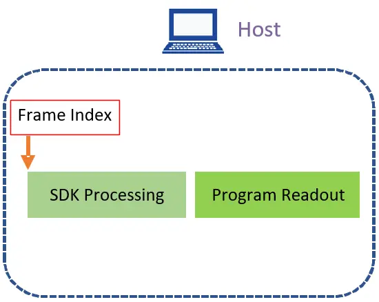
After obtaining one frame, the SDK will temporarily store the frame in the buffer, preparing for the application program reading. If the application program does not read in time, the SDK could overwrites the old frame with the new one, resulting a frame loss. Through the frame index, the user can determine whether frame loss happen caused by host process scheduling or high CPU load.

As shown in the figure above, the SDK received frames 1,2,4 in a row, so we know that a frame 3 in the middle was not read correctly. From the principle of frame index generation, it can be known that if frame loss occurs, there must be a problem with the application program reading on the host side.
Obtaining timestamp and frame index
The timestamp and frame index of the Vzense camera image are in the ScFrame structure.
typedef struct
{
    uint32_t      frameIndex;        //The index of the frame.
    ScFrameType   frameType;         //The type of frame.
    ScPixelFormat pixelFormat;       //The pixel format used by a frame.
    uint8_t*      pFrameData;        //A buffer containing the frame’s image data.
    uint32_t      dataLen;           //The length of pFrame, in bytes.
    uint16_t      width;             //The width of the frame, in pixels.
    uint16_t      height;            //The height of the frame, in pixels.
    uint64_t      deviceTimestamp;   /*The timestamp(in milliseconds) when the frame be generated
                                       on the device. Frame processing and transfer time are not
                                       included.*/
} ScFrame;The timestamp and frame index can be obtained through the scGetFrame interface. The sample code is as follows:
//depthFrame for example.
		if (1 == FrameReady.depth)
		{
			status = scGetFrame(deviceHandle, SC_DEPTH_FRAME, &depthFrame);
			if (depthFrame.pFrameData != NULL)
			{
				cout << "scGetFrame status:" << status << "  "
				<< "frameType:" << depthFrame.frameType << "  "
				<< "deviceTimestamp:" << depthFrame.deviceTimestamp << "  "
				<< "frameIndex:" << depthFrame.frameIndex << endl;
			}
}Frame latency
Latency in one frame
According to the processing procedure of one frame, the delay of the camera is composed of the following parts:
| Part | Description | Factors | |
| Exposure | Camera | The acquisition of one frame image is completed by exposure | 1. Exposure time setting 2. HDR function (enable HDR, time consumption increases) 3. WDR function (enable WDR, time-consuming increase) |
| ISP processing | Camera | Depth map calculation, IR map calculation, RGB image conversion, RGB image coding, image filtering, distortion reduction and so on | 1. RGB image resolution (the higher the resolution, the longer the time consumption); 2. Depth image resolution (the higher the resolution, the longer the time consuming); 3. Filter switch (open filter, time-consuming increase) 4. HDR function (enable HDR, time consumption increases) 5. WDR function (enable WDR, time consumption increase) |
| Transmition | Network device between camera and host | Transfer data from the camera to the host computer | 1. Network device performance (such as network card, network cable, etc.) 2. Host network load |
| SDK processing | Host | Point cloud conversion, image alignment, RGB image decoding, etc | 1. Host performance 2. User application multithreaded design |
| Program readout | Host | Read the image from the SDK buffer | 1. Host performance 2. User application multithreaded design |
Test methods of frame latency
The following part will explain and exemplify how to perform one frame latency. In the below tests, two types of latency are tested: total single-frame latency, and latency excluding exposure time (end of exposure to application program reading).
Test steps:
1. Enable the camera’s NTP or PTP timing function.
Please refer to application notes “AN05-NTP function settings for Vzense 3D Time of Flight (ToF) camera” and “AN06-PTP function settings for Vzense 3D Time of Flight (ToF) camera“.
If you only need to test the total delay of a single frame, you can skip this step.
Note: Some product camera do not support NTP, PTP clock synchronization at the moment.
2. Timestamp printing
Sample code:
BaseSDK/Windows/Samples/Base/NYX650/SingleFrameDelayTest.
1) Windows
Use the ftime function to get a converted millisecond UNIX timestamp.
Sample code is as follows:
#include <time.h>

/*
  omit some code
*/

for (int i = 0; i < number; i++)
{
	timeb timeStart, timeEnd;
	status = scSoftwareTriggerOnce(deviceHandle);
	ftime(&timeStart);//record the start timestamp
	if (status == ScStatus::SC_OK)
	{
	}
	else
	{
		cout << "[scSoftwareTriggerOnce] fail, ScStatus(" << status << ")." << endl;
		continue;
	}

  //If the device is set with software trigger parameter, the ready time needs to be extended, so the setting here is 15000ms.
	status = scGetFrameReady(deviceHandle, 15000, &frameReady);
	if (status == ScStatus::SC_OK)
	{
	}
	else
	{
		cout << "[scGetFrameReady] fail, ScStatus(" << status << ")." << endl;
		continue;
	}
  //depthFrame for example.
	if (1 == frameReady.depth)
	{
		status = scGetFrame(deviceHandle, SC_DEPTH_FRAME, &depthFrame);
		if (status == ScStatus::SC_OK)
		{
			if (depthFrame.frameIndex % 10 == 0)
			{
				cout << "SC_DEPTH_FRAME <frameIndex>: " << depthFrame.frameIndex << endl;
			}

			ftime(&timeEnd);//record the end timestamp
			endTimestamp = timeEnd.time * 1000 + timeEnd.millitm;
			startTimestamp = timeStart.time * 1000 + timeStart.millitm;
			deviceTimestamp = depthFrame.deviceTimestamp;
			frameInterval = endTimestamp - startTimestamp;
			frameIntervalNTP = endTimestamp - deviceTimestamp;

			//If the delay time is greater than 2000, it is considered that NTP is not enabled.
			if (frameIntervalNTP > 2000)
			{
				csvWriter << depthFrame.frameIndex << "," << frameInterval << ",N/A" << endl;
			}
			else
			{
				csvWriter << depthFrame.frameIndex << "," << frameInterval << "," << frameIntervalNTP << endl;
			}
		}
		else
		{
			cout << "[scGetFrame] fail, ScStatus(" << status << ")." << endl;
		}
	}

	//The time interval between two triggers should be greater than
	//the time interval between the two frames generated.
	this_thread::sleep_for(chrono::milliseconds(1000 / frameRate));
}2) Linux
Use the clock_gettime function to get a converted millisecond UNIX timestamp.
Sample code is as follows:
#include <time.h>

/*
omit some code
*/
for (int i = 0; i < number; i++)
{
	timespec timeStart, timeEnd;
	status = scSoftwareTriggerOnce(deviceHandle);
	clock_gettime(CLOCK_REALTIME, &timeStart);//record the start timestamp
	if (status == ScStatus::SC_OK)
	{
	}
	else
	{
		cout << "[scSoftwareTriggerOnce] fail, ScStatus(" << status << ")." << endl;
		continue;
	}

    //If the device is set with software trigger parameter, the ready time needs to be extended, so the setting here is 15000ms.
	status = scGetFrameReady(deviceHandle, 15000, &frameReady);
	if (status == ScStatus::SC_OK)
	{
	}
	else
	{
		cout << "[scGetFrameReady] fail, ScStatus(" << status << ")." << endl;
		continue;
	}
	////depthFrame for example.
	if (1 == frameReady.depth)
	{
		status = scGetFrame(deviceHandle, SC_DEPTH_FRAME, &depthFrame);
		if (status == ScStatus::SC_OK)
		{
			if (depthFrame.frameIndex % 10 == 0)
			{
				cout << "SC_DEPTH_FRAME <frameIndex>: " << depthFrame.frameIndex << endl;
			}

			clock_gettime(CLOCK_REALTIME, &timeEnd);//record the end timestamp
			endTimestamp = timeEnd.tv_sec * 1000 + timeEnd.tv_nsec/1000000;
			startTimestamp = timeStart.tv_sec * 1000 + timeStart.tv_nsec/1000000;
			deviceTimestamp = depthFrame.deviceTimestamp;
			frameInterval = endTimestamp - startTimestamp;
			frameIntervalNTP = endTimestamp - deviceTimestamp;

			//If the delay time is greater than 2000, it is considered that NTP is not enabled.
			if (frameIntervalNTP > 2000)
			{
				csvWriter << depthFrame.frameIndex << "," << frameInterval << ",N/A" << endl;
			}
			else
			{
				csvWriter << depthFrame.frameIndex << "," << frameInterval << "," << frameIntervalNTP << endl;
			}
		}
		else
		{
			cout << "[scGetFrame] fail, ScStatus(" << status << ")." << endl;
		}
	}

	//The time interval between two triggers should be greater than
	//the time interval between the two frames generated.
	this_thread::sleep_for(chrono::milliseconds(1000 / frameRate));
}The results of the implementation are as follows:
The above method allows you to test the latency of the current system for several times.
It can be viewed in the generated “SingleFrameDelayTest.csv” file, as shown in the following table:
| frameIndex | TotalDelay | ExcludeDelayofExposure |
| 1 | 98 | 42 |
| 2 | 107 | 52 |
| 3 | 117 | 62 |
| 4 | 112 | 57 |
| 5 | 110 | 55 |
| 6 | 93 | 38 |
| 7 | 103 | 47 |
| 8 | 89 | 34 |
| 9 | 113 | 57 |
| 10 | 111 | 55 |
The two test indicators for this test (10 frames of images) are known from the generated data as follows:
a) The total latency of a single frame is about 105ms.
b) The latency excluding exposure time is about 50ms.
Vzense ToF camera latency test data
Take NYX650(B26) + ScepterSDK(v24.12.2) as an example, the ToF exposure time is 5ms, RGB resolution is 640 x 480, Depth2RGB alignment is on, and the delay test data of Depth and RGB image after getting the alignment is as follows:
| Platform | Exposure + transmission | ISP processing | Network transmission | SDK Processing | Total Latency |
| RK3588 | 13ms | 65ms | 20ms | 36ms | 134ms |
| Nvidia Xavior | 13ms | 65ms | 10ms | 30ms | 118ms |
The latency of DS series products will be a bit higher compared to NYX. Take DS86(B21) + ScepterSDK(v24.12.2) as an example, ToF exposure time 4ms, RGB resolution 640 x 480, open Depth2RGB alignment, get the aligned Depth and RGB image latency test data is shown in the following table:
| Platform | Exposure + transmission | ISP processing | Network transmission | SDK Processing | Total Latency |
| RK3588 | 56ms | 84ms | 38ms | 47ms | 225ms |
| Nvidia Xavior | 56ms | 84ms | 22ms | 41ms | 203ms |
Latency optimization
If, after testing, it is found that the overall delay cannot meet the application requirements, it can be adjusted and optimized from the following perspectives:
1.Image resolution: The larger the image resolution, the larger the amount of data that needs to be processed, so the difference in resolution has the greatest impact on latency. It is recommended to choose a smaller resolution, such as 640×480, if the business allows.
2. System platform: the performance of the system platform directly affects the efficiency and performance of the SDK, so try to choose a platform that meets the requirements, as well as try to balance the resources of other processes on the camera SDK.
3. Point cloud conversion: point cloud conversion involves a large number of float operations, consumption is large, try to reduce the number of point cloud conversion can improve efficiency. For example, we only convert point cloud in ROI(region of interest) area, and don’t convert the whole map.
4. Filter switch: According to the business requirements, you can turn off some of the filter switches to reduce resource consumption and improve latency.
5. Camera model: Vzense camera has different models, different models of cameras because of different principles, different ways of realization, there will be delay differences.


